- Loading…

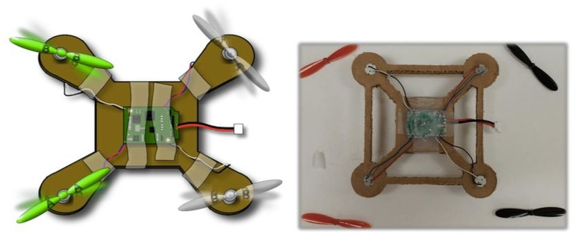
The law defines an unmanned aircraft system (UAS) as “an aircraft that is operated without the possibility of direct human intervention from within or on the aircraft.” An unmanned aircraft does not have a human pilot onboard, but instead is controlled from the ground. UAS are most commonly referred to as drones, but also include radio-controlled, fixed-wing aircrafts, helicopters, rotorcraft models, and quadcopters. Students will learn about the science of flight and integrate digital fabrication technologies while designing and building their own palm sized quadcopter.
[Student] Prerequisite skills/knowledge
Students should be moderately comfortable in a Fab Lab environment and be capable of some amount of self-guided work. They should have some experience with the following software, processes and equipment:
Key Vocabulary:
Hardware / Software
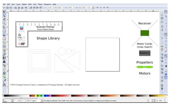
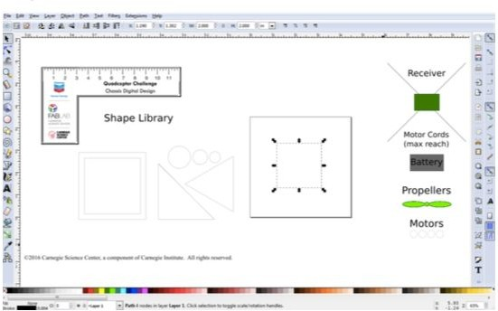
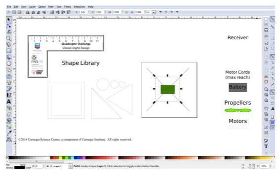
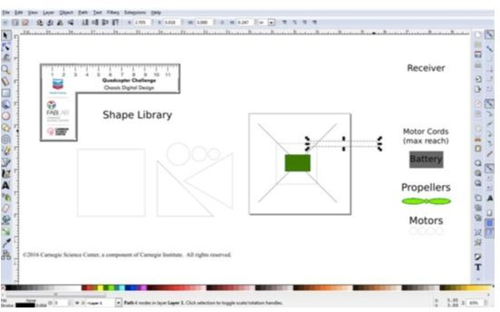
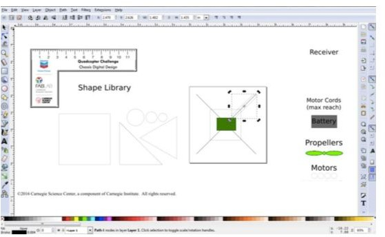
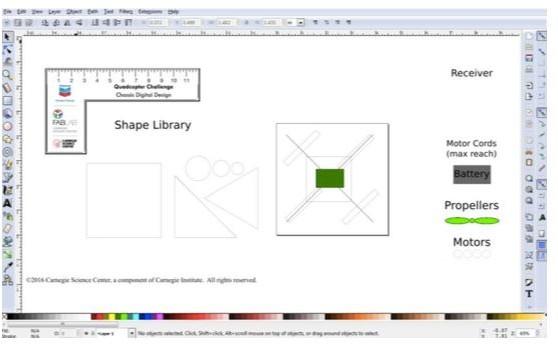
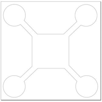
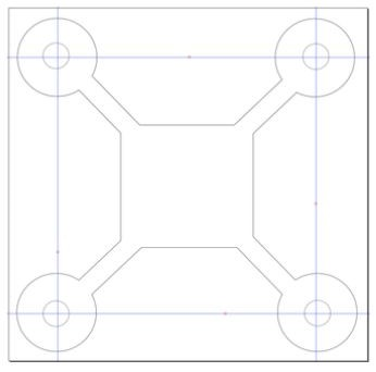
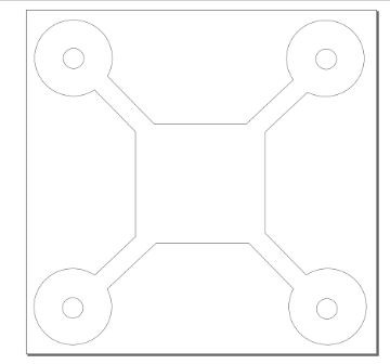
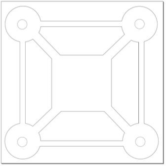
Design Files attachment: QCC Chassis Template.svg
Materials List
General Supply Checklist
Quadcopter Project Materials List
Note: These materials can be purchased directly from Hubsan, at https://www.hubsan.com/. However, their stock tends to be low. It is faster and cheaper to source and purchase parts through domestic importers, found on Amazon. Day-to-day stock and direct links continually change. As long as parts are purchased for the H107L model, they should work without issue. When purchasing, keep in mind that Hubsan sells many different models of quadcopters and drones, so make sure to purchase parts for the H107L.
Shared Materials
Per Quadcopter
Steps
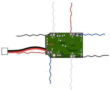
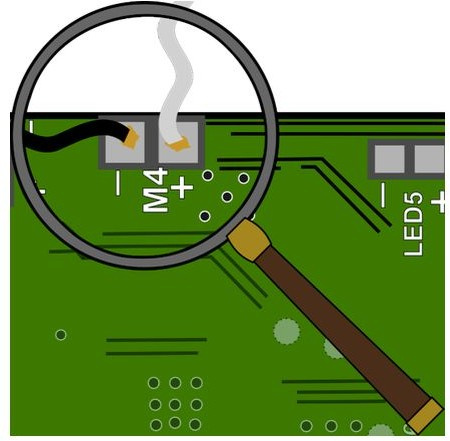
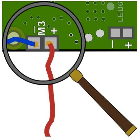
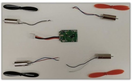
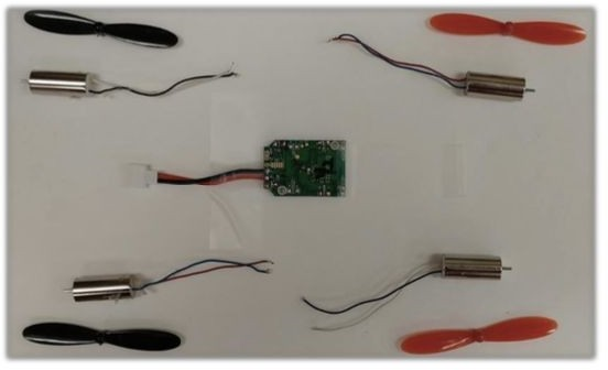
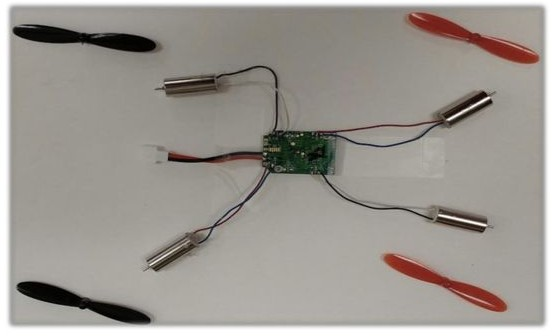
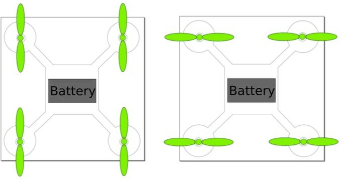
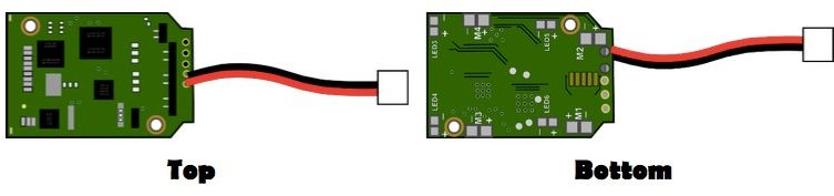
I. Assembling the Internals
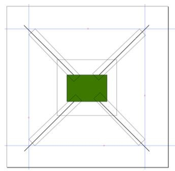
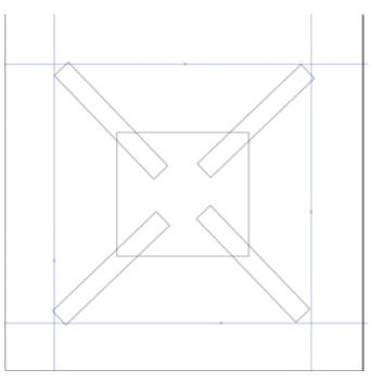
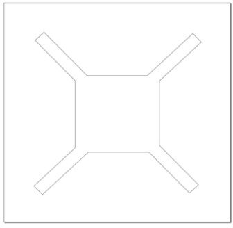
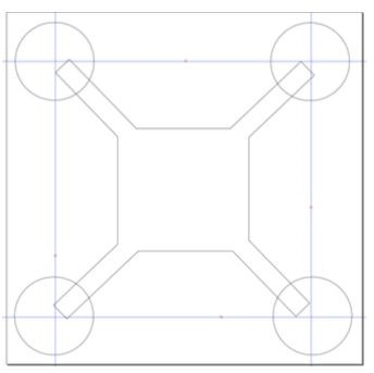
II. Chassis Digital Design
III. Making Prototypes
IV. Testing and Iteration
V. The Quadcopter Challenge
I. Assembling the Internals – 2 Hours
II. Chassis Digital Design – 2 Hours
III. Making Prototypes – 2 Hours
IV. Testing and Iteration – 3+ Hours
V. The Quadcopter Challenge – 2+ Hours
Differentiated Instruction (Extension Activities)
3D printing can be added to make several of the component on the quadcopter if the tools and time allow. Design software could be either Tinkercad, Fusion 360, Solidworks or any other package with similar capabilities. These parts include:
Having trouble? Let us know by completing the form below. We'll do our best to get your issues resolved quickly.
"*" indicates required fields
Thank you for your fab contribution!