- Loading…

Based on the initiative developed by a team of engineers, biologists, and designers of the European Space Agency and their partner Border Labs, the Fab Lab Onl’Fait is developing the Astroplant programme, working with Swiss secondary school students to build “plant characterization” hydroponics growboxes where to grow edible plants such as lettuce and basil. Each greenhouse is equipped with different sensors to monitor, control the environment during the growth cycle of plants and collect data about air and water temperature, humidity, light and level of CO2 . The data collection system is based on a Raspberry Pi board with a custom PCB to integrate all the required sensors and electronics. Students will design experiments and document the plant grow to optimize the experimental set-up. Most importantly we will share the data collected with the other citizen scientists and the ESA scientists.
ASTROPLANT MAKER KIT
AstroPlant components
AstroPlant Extension Shield / Integrator
AstroPlant LED
Off-the-shelf components
Raspberry Pi Zero WH
MicroSD Card
Raspberry Pi Zero Camera cable
LCD Display 16*2 – with I2C Backpack
Raspberry Pi 40 pins GPIO cable
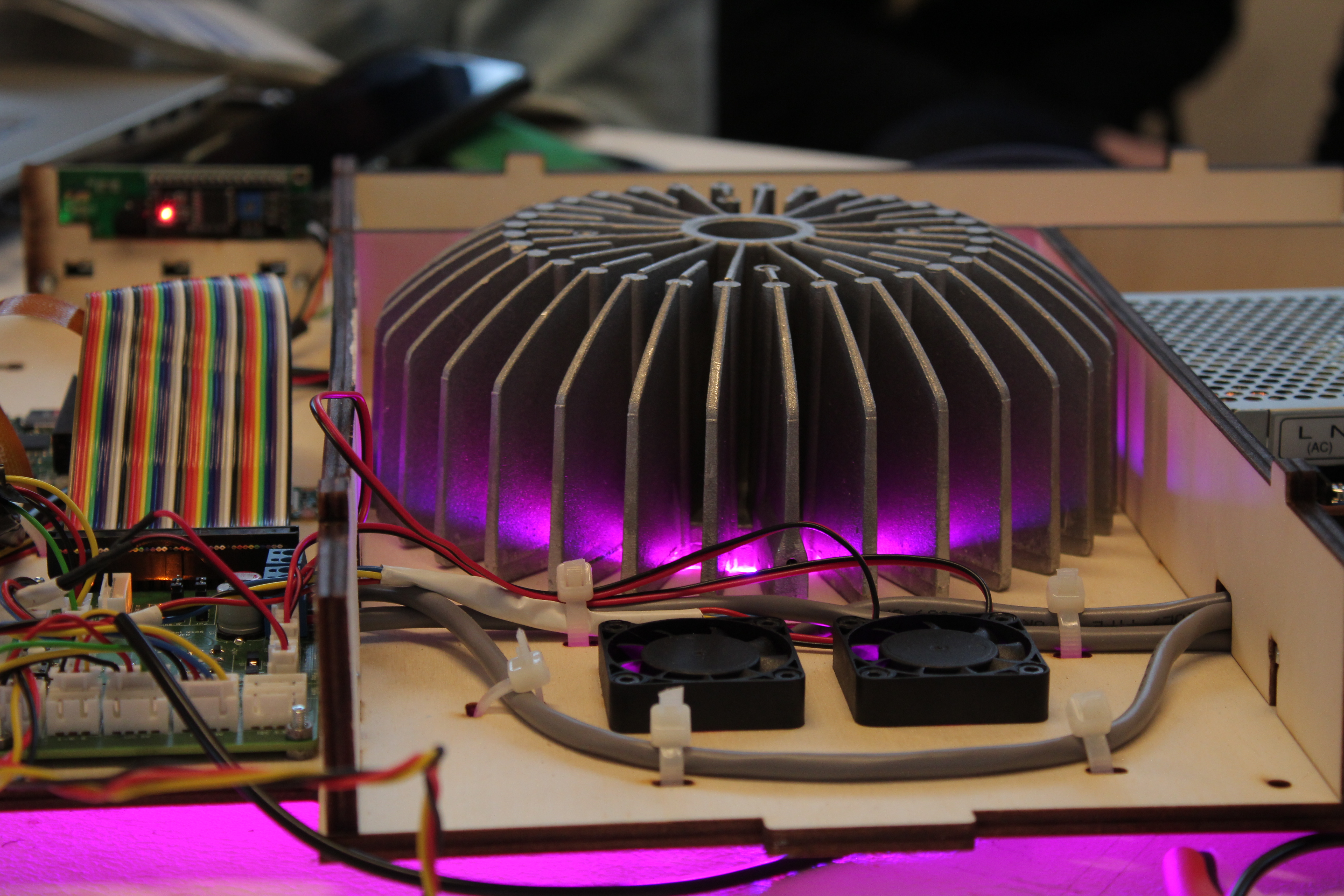
3 x 24V DC 40mm Cooling Fan
Heat Sink
AC/DC
Power cable
Sensors
BH1750 16bit Digitale I2C Light Sensor Module
DS18B20 TO-92 Thermometer Temperature Sensor – Waterproof
AM2302 (DHT22) temperature-humdity sensor
MH-Z19 infrared co2 sensor for co2 monitor MH-Z19B
Raspberry Pi Camera Board V2 – 8MP
Wiring and connectors
The wiring is already cut and have connectors, so assembly is quite easy.
Water Farm
Hydroponics kit + pump from GHE
Manual and support
Astroplant provides an assembly manual and growth protocol to start your research. Our software is available online.
Casing
Create your own casing from wood. Follow our open source design to laser cut your casing.
Plant kit
Grains, fertiliser, clay pebbles, pH test kit
Time
Team up with a Fab Lab and start building your own AstroPlant growbox.
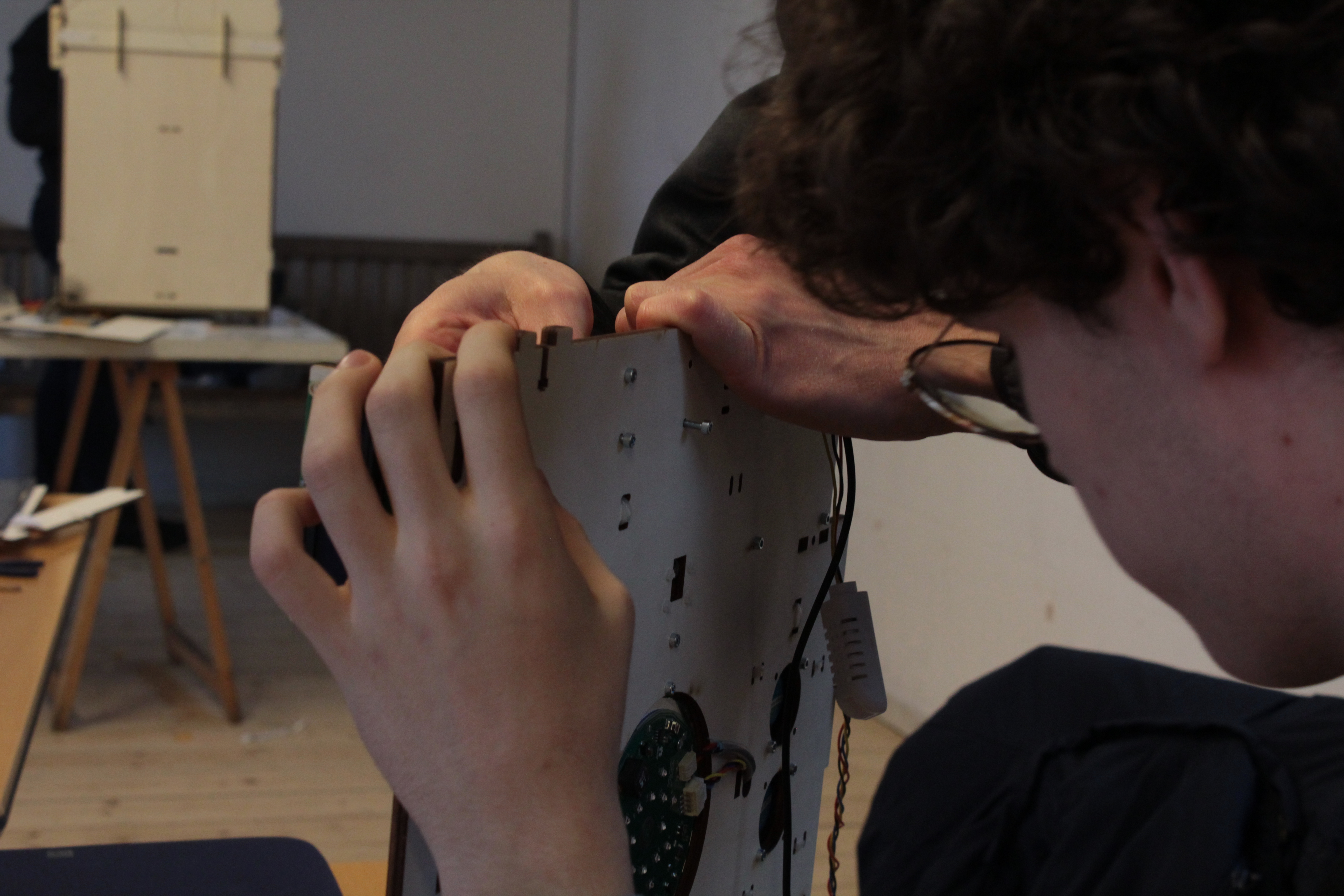
Students will be introduced to 2D vectorial drawing to personalise the parts of the wooden casing to cut and engrave with a laser cutter. They will assemble it with screws and 3D print a few additional parts.
Please refer to Astroplant GitBook for the
https://astroplant.gitbook.io/join-mission/astroplant-hardware-beta/casing-assembly-v5.2
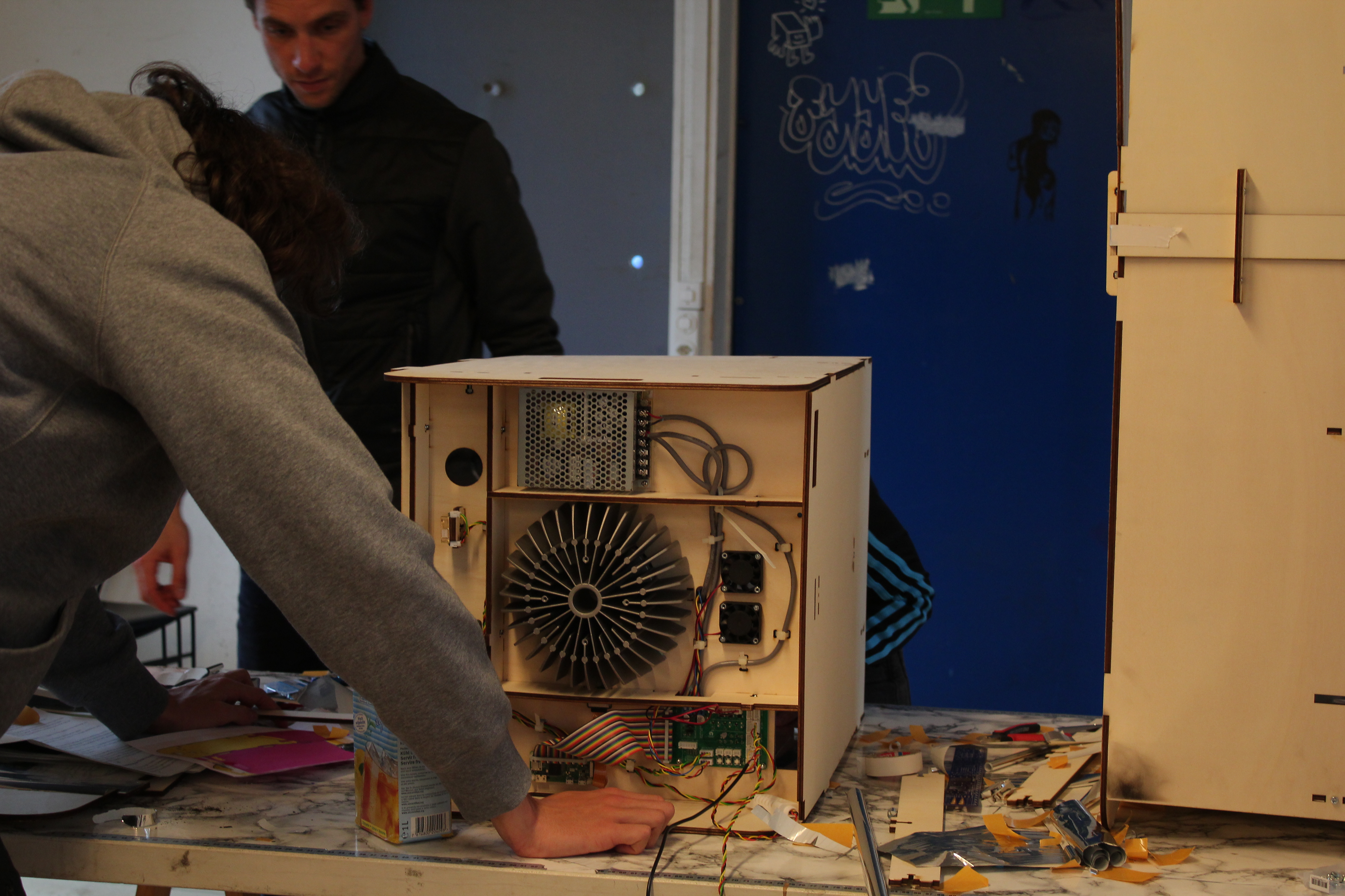
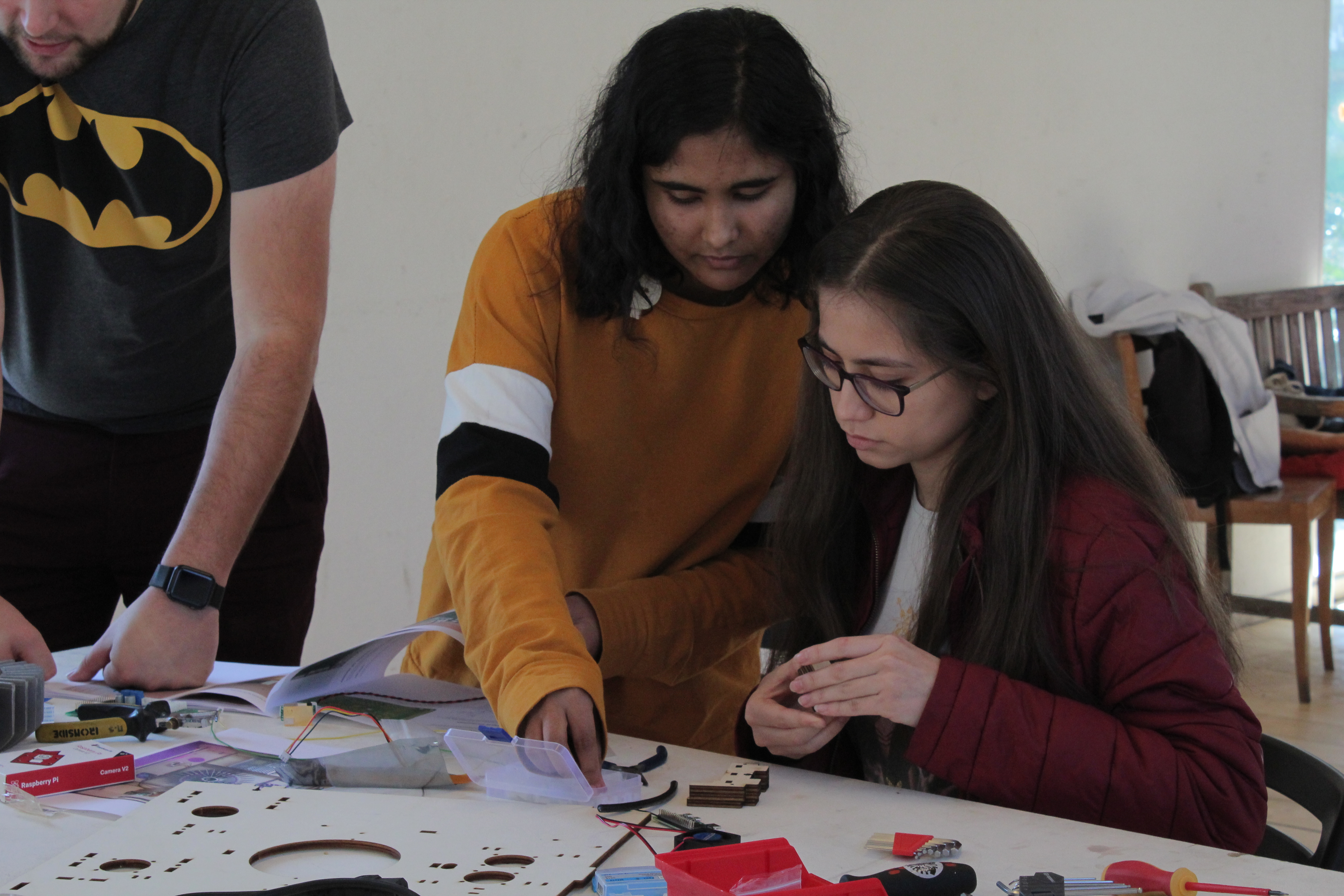
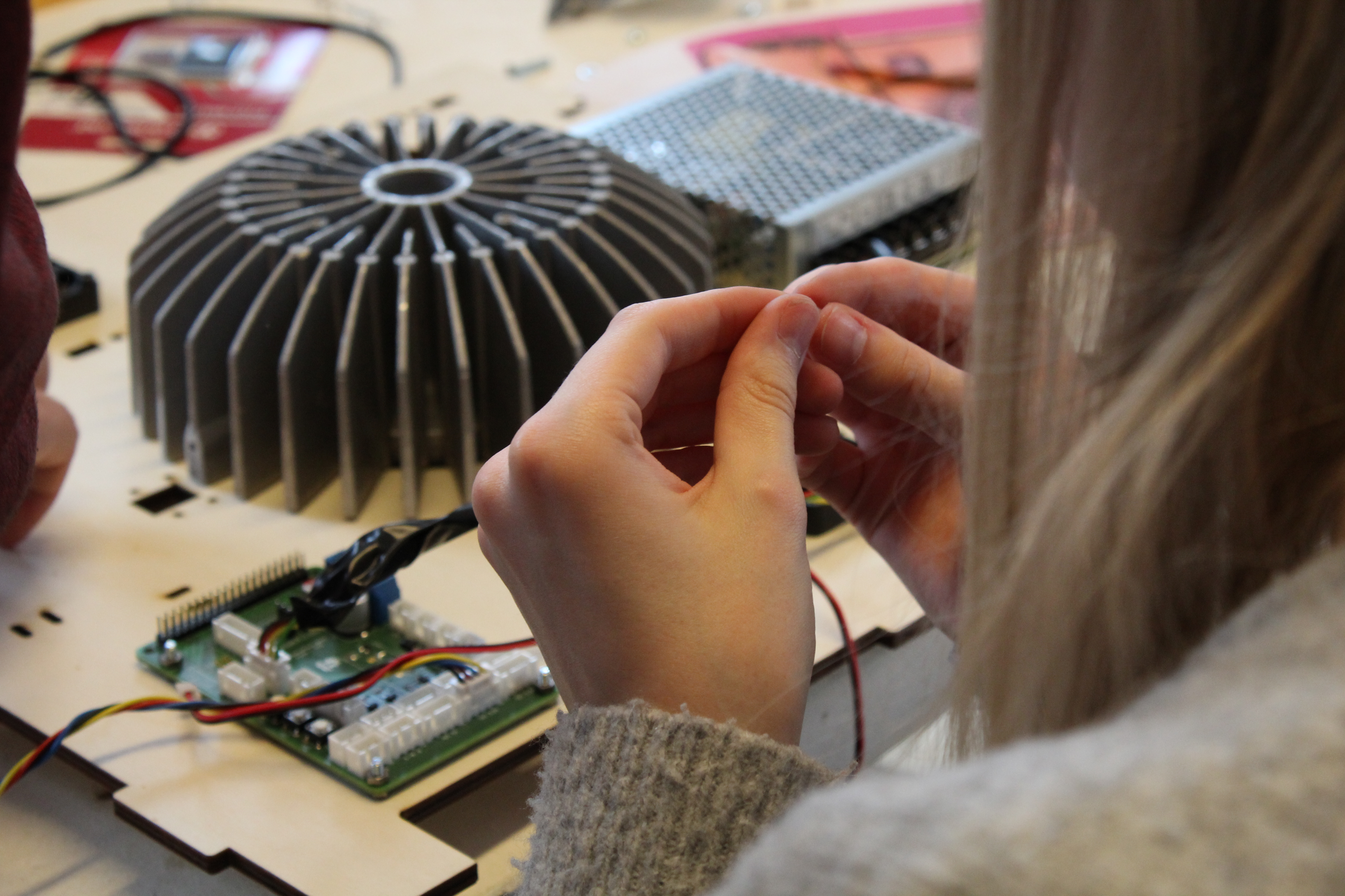
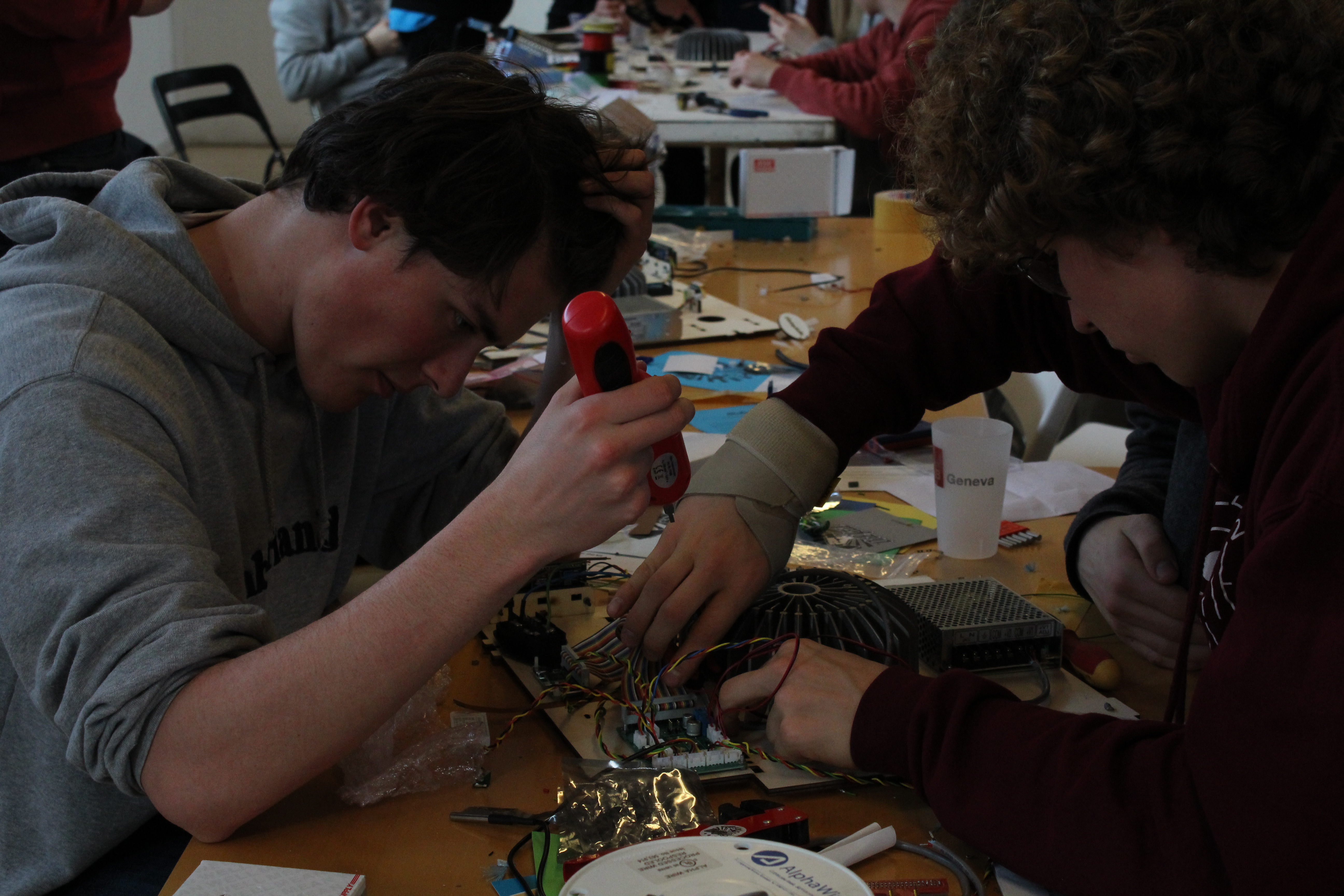
In this part of the lesson (3-5 hours), students will assemble the hardware of the Astroplant groboxes. They will solder and connect components, including sensors, a Raspberry Zero, an extension shield and power supply.
The following graphical overview showcases the peripheral connections to the extension board.

See the schematic below for the location of each peripheral device on the extension board.

For detailed extension board schematics refer to https://github.com/VincentFrangi/astroplant-extension-board-mk0-6/blob/f58b9c0ac6792eb3fa5ac8913f5183f49b7c605e/schematics.pdf
For detailed LED schematics refer to https://github.com/VincentFrangi/astroplant-led-aluminum/blob/d76a4e8f7f76e83b55a7287c2d851546948c60c2/Schematics.pdf
To avoid overheating add a jumper between RPi and ln and Power RPi and JP2.

By default the extension board is typically manufactured without solder bridges, however for the pilot boards J13 (see image below) has typically a solder bridge. Please verify this.


As shown in the figure below J13 already has a bridge for two fans on the +24V line. For J15 connected to spare solder an additional bridge for a 3rd fan. This 3rd fan is used for pushing air towards the co2 sensor. Optionally you may wish to connect another 24v device such as a pump, then solder the bridge for J14.

All the sensor and actuators are connected via connectors from the JST XH family. It is recommended to use a PA-09 crimping tool for assembling the JST connectors.
The CO2 sensor is of type MH-z19 with an UART interface.

On the sensor solder the 2-pin JST males to the connections shown in the table above.

Use 22AWG cables: Red (5v), Black (GND), Rx (White), Tx (Green). Connect on the wires crimp pins with the PA-09 tool (use 1.9 mm and 1.6mm) on the sensor side.

Use the Spiral Wire wrap to wrap the wires together before connecting the other side.

Now it is time to connect the 2x 2-pin JST female on one side, keep in mind the table connections!

Now connect the 4-pin JST female on the other side and hook up to the board (Keep in mind the described table connections!, RX goes to TX on board and TX to RX). See image below.

The Lux sensor is of type BH1750/GY-30 and uses an I2C interface.

Solder on the sensor the JST 5-pin male.

Use 22AWG cables: Red (5v), Black (GND), SCL (Green), SDA (Yellow). Connect on the wires crimp pins with the PA-09 tool (use 1.9 mm and 1.6mm) on the sensor side.
Connect the 5-pin JST female on one side, keep in mind the table connections!

In turn apply the spiral wrap and crimp the other end of the wires.

Connect the 4-pin JST female to the wire and plug the connector in the board. (check table for connections).

The relative humidity and temperature sensor used in the AstroPlant kit is of type AM2302 and uses the 1-wire interface. This sensor is the same as a DHT22, but has an integrated pull-up resistor.
Se spiral wrap on the existing wire and crimp the wires (see image below).

Connect the wires to the 3-pin JST female and attach to the board.

The water temperature sensor to be connected is of type DS18B20 and uses the 1-wire interface (Dallas/Maxim).

Connect the 3-pin JST female pin and insert into the board (data on GPIO pin 04).

The LCD screen is of type 16×2 + I2C backpack standard screen. See table below.
On the other side set spiral wrap and construct the 4-pin JST connection for the extension board.
Plug it into the extension board in the I2C 5V section.

The fans have a dimension of 10*40mm and our powered through 24VDC. The fans are typically supplied with a JST-connector. Connect the fans to the extension board. Connect an additional fan to the spare socket. Keep in mind that the solder bridges are correct.

The LED panel is controlled via PWM signals on the extension board. You’ll need 22 AWG wires and 2x 4-pin female JST connectors.
Crimp the 22 AWG wires (colors: blue, red, yellow) and connect one 3-pin female connector on one end. In turn insert the connector into the LED.

Put spiral wrap on the wires and crimp the other side.

Crimp and connect the other 3-pin female connector to the board.

After you can detach the JST LED connector on the LED panel, as we need to glue the LED panel to the heatsink with thermal adhesive in section Assemble LED power.
Dangerous voltage/current levels. We bear no responsibility with respect to breakdowns or damages due to insufficiently safe connections. Refer to the Cern OHL v1.2 license at the top of this page. We highly advice to perform assembly with an experienced electrical engineer.
See below an overview of the power supply connections:

Technical overview (units in mm2 minimum thickness)
Recommended tools to use:
For the power supply we use the Meanwell RD 65B:
The fuse socket connector can be ordered here:
Connectors:
Start with the fuse socket connector firstly. Make sure 2x 250v 10A fuses are inserted in the fuse socket.

Open the lid and insert two fuses of 240v 10A.
See the picture below for the socket connections.

Use 2x blade connectors and 3x spade connectors. Cut 2x 1.5mm2 wires (blue, brown) for about a length of 9 cm and 1x 1.5mm2 wire (yellow-green) for a length of 12 cm. Crimp 2x the blade connectors for the blue and brown wire (remove 5.2 mm of isolation). Leave the yellow-green wire without a blade connector as that wire should be soldered to the fuse socket. Next crimp on the other side the spade U-type connector (remove 5 mm of isolation) for all wires. See figure below for an example of the final result:

Test the connections with a multi-meter. 1) perform continuity test between ground and electrical phase, 2) test if there is not short circuit in any of the power sources, 3) test the voltage levels on V1 and V2.
Adjust voltage with screw if the voltage levels are not 5v (+V1) and 24v (+V2).
Firstly make sure that the heatsink is clean and doesn’t contain any dust or grease. Position the heatsink according to this picture (take note of the heatsink screw holes):

Take off the LED panel and carefully apply the heatsink adhesive to the LED panel and place it on the heatsink according to the placement picture above. If you use the wakefield adhesive wait 5-46 minutes at room temperature.
The next step is to create the wires and connectors.
Use 18AWG/0.75mm2 single core wires.
Cut the red and black wires for a length of 36 cm. Remove 5 mm of isolation on both sides. Crimp 2x spade connectors on one side of the black and red wire. Solder the single core to the spade connector:

The other side of the wire goes directly into the Wago connector on the LED panel.
To power the fans you’ll need 16AWG/1mm2 wires, a Ferrule crimping tool and Spade crimp tool. In addition 2x spade and 2x ferrule connectors.
Meanwell AC/DC converter connections
Remove 5 mm of isolation on one side and 8 mm on the other side. Crimp the spade connectors one one side (5mm) of the two wires and crimp the ferrule on the other side (8mm). If you use the same ferrule crimp you can crimp at 1.5 mm.

Similarly to the Assemble fan power section, we create two wires with spade and ferrule connectors. The only difference is the cable length.
Meanwell AC/DC converter connections
Connects to:
Cable length – color
+V1
5v terminal extension board
39 cm – Red
COM
5v terminal extension board
39 cm – Black
A 40-pin GPIO cable (female/female) is needed to connect the two boards. See images below:

The red-side (top) of the cable connects to J2 on the extension board and 3.3V/5V on the Raspberry Pi.
Note that the a GPIO rainbow cable has a different color scheme. The red-side shown above is in most cases another color (there can be inconsistency between rainbow cables color schemes). The most important bit is the correct orientation.

GPIO cables tend to bend the GPIO-pins on the board be careful when attaching the cable.

This option assumes that you have already connected the power supply to the extension board. This is the recommended option.
Test
This option assumes that you have already connected the power supply to the extension board
Setup
RPi x[xx] In
In case you have a RPi USB cable at your disposal you can follow this section. This is only suitable if you don’t wish to control actuators.
RPi [xx]x In
In this part of the lesson (1-2 hours) students will setup the software and configure it
To install the image you have two options:
1) install the software client image (recommended). Download the image here:
https://sidneyniccolson.stackstorage.com/s/xb4WVGGJOzee5Ye
2) install the basic image. Download the image here:
https://sidneyniccolson.stackstorage.com/s/3t9VCxXU58GhB8c
This image contains all needed libraries and has a chromecast-like internet setup configuration.
Make sure all your peripherals are connected before continuing.
Make sure an SD card is inserted in your computer and startup Etcher. In turn select the downloaded image and flash to the SD card.

Once flashed insert the SD card into the Raspberry Pi port and turn on the power.
Go to https://my.astroplant.io/accounts/register/and fill in your credentials. You will receive an activation mail. Keep in mind that it can be in your spam mail!
Once activated you’ll see this screen:

Click on add kit. Generate your secret keys and store it somewhere save.
Go to the peripheral devices tab:

Start with adding the CO2, light, water temperature sensors, set your preferred sensor names and keep everything else on default. For the relative humidity and ambient temperature sensors (DHT22), fill in pin number 17 in the case the default value is 22.

Due to the possibility of loosing the internet connection it is recommended to make sure that local data logging is set. Configure another peripheral device to enable local data logging.

Next make sure to set your location and data access to public if you want to participate in AstroPlant-ESA experiments.

Click on the map to set your location. In turn click save.

Make sure “show on map” and “public dashboard” is selected.
That’ll be it!
Assuming your image is inserted in the Rasberry Pi, look under your computer’s wifi connections for “AstroPlant Setup [xxxx] “.
Navigate tohttps://10.0.0.1or http://ww.astroplantsetup.com.
Select the WiFi connection you’d like your Raspberry Pi to connect to from the drop down list and enter its wireless password on the page provided. If no encryption is enabled, leave the password box blank. You may also manually specify your network information by clicking on the “manual SSID entry ->” link.

Leave “API url” and “Websocket URL” under the default settings.

Fill in your authentication credentials you received from the my.astroplant.io.

If you have the LCD connected click the checkbox and fill in “0x27”. If you are unsure what the address is check the label on top of the LCD screen for the address. Alternatively you can leave the option blank and uncheck the box.

Click the “Submit query” button.
The next page will guide you through actuator setup if desired.

Check the button if you wish to setup the actuator control.
It is recommended to never set the intensity to 100% if you have the official AstroPlant LED panel. The total lifetime of the LEDs could be potentially reduced at 100%. Detailed spectrometer results coming soon!
You can use the default settings if you wish. However an initial recommended setting can be found in the AstroPlant Growth Protocol. If you choose to conduct an experiment with one of the LED light groups completely off, you need to set the value to ‘0.0’, instead of ‘disabled’.
You can leave the GPIO pin numbers on default. And enter your desired intensity and schedule.

At this point your Raspberry Pi will reboot and connect to the wifi specified and in turn AstroPlant’s software service will be automatically started. This process can take about a minute. Visit your dashboard athttps://my.astroplant.io/.

If you wish to reset your wifi connection, schedule and AstroPlant credentials, press the SW3 (GPIO7) button on the extension board for about 15 seconds. This will reboot the device and enable you to reconnect with your computer.
If you wish to shutdown your system, press the SW2 (GPIO6) button on the extension board for about 15 seconds. After a few seconds you can switch off the power supply (AC/DC converter).
The CO2 sensor has auto-calibration. This means that if the readings are incorrect (typically below 400 ppm) it is advised to place the kit near a window. Optionally open the toppanel.
You may skip this section and continue to “Setup your actuator control” if you installed the software client image.
The basic image contains all libraries pre-installed. However you’ll need to configure your internet and web-applications settings manually.
Make sure an SD card is inserted in your computer and startup Etcher. In turn select the downloaded image and flash to the SD card.
Once you’ve burned/etched the Raspbian image onto the microSD card, connect the card to your working PC and you’ll see the card being mounted as “boot”. Inside this “boot” directory, you need to make 2 new files. You may need to re-insert the SD card to see the “boot” folder. Create a file named wpa_supplicant.conf. This time you need to write a few lines of text for this file, adjust the file below accordingly.
ctrl_interface=DIR=/var/run/wpa_supplicant GROUP=netdev
update_config=1

network={
    ssid="your network"
    psk="your pass"
}
Finally insert the SD card in the Raspberry Pi.
Follow inhttps://astroplant.gitbook.io/join-mission/building-astroplant/building-your-software-from-scratchsteps 4 and 9. For SSH (step 4) your user is “pi” and password is “AstroPlantYS”.
Building your software from scratch
/astroplant-software/building-your-software-from-scratch
At this point in time, we have not integrated the actuator control in the web-application. A simple job scheduler (cron) is used to schedule actuators.
Follow this section if you followed option 1 or 2 and have the power supply and actuators connected.
Use a screen and keyboard if you wish to perform this step directly in the Raspberry Pi. Alternatively use SSH (see https://astroplant.gitbook.io/join-mission/building-astroplant/building-your-software-from-scratch#step-4-headless-connecting-to-the-rpi-via-ssh). Your user is “pi” and password is “AstroPlantYS”.
Firstly setup your timezone in raspi-config. Enter the following in the terminal:
$ sudo raspi-config
Go to Localisation options.

Hit change time zone and select your geographic area:

Select your city:

The next step is to enable actuator control. For this you can use the AstroGeeks package already installed. Manually adjust the config.json GPIO settings in the /home/pi/astrogeeks-actuator-control folder to the following settings if you own the official AstroPlant LED panel.
Config.json example below.
{
 "actuators": [
     { "className": "Led", "name": "Led.Blue", "pin": 21 },
     { "className": "Led", "name": "Led.Red", "pin": 20 },
     { "className": "Led", "name": "Led.FarRed", "pin": 18 },
     { "className": "Fan", "name": "Fan", "pin": 16 },
     { "className": "Fan", "name": "Sensor_Fan", "pin": 19 }
 ]
}
Setup a crontab with the following command
$ sudo crontab -e
This is an example you can use:
@reboot cd /home/pi/astrogeeks-actuator-control && ./controld

# on from 19:00 till 19:59
* 19 * * * cd /home/pi/astrogeeks-actuator-control && ./control "Led.FarRed" 20
# off from 20:00 till 18:59
* 20-23,0-18 * * * cd /home/pi/astrogeeks-actuator-control && ./control "Led.FarRed" 0.0
# off from 20:00 till 5:59
* 20-23,0-5 * * * cd /home/pi/astrogeeks-actuator-control && ./control "Led.Blue" 0.0
* 20-23,0-5 * * * cd /home/pi/astrogeeks-actuator-control && ./control "Led.Red" 0.0
# off from 4:00 till 5:59
* 4-5 * * * cd /home/pi/astrogeeks-actuator-control && ./control "Fan" 0
* 4-5 * * * cd /home/pi/astrogeeks-actuator-control && ./control "Sensor_Fan" 0
# on from 06:00 till 19:59
* 6-19 * * * cd /home/pi/astrogeeks-actuator-control && ./control "Led.Blue" 10
* 6-19 * * * cd /home/pi/astrogeeks-actuator-control && ./control "Led.Red" 20
# on from 6:00 till 3:59
* 6-23,0-3 * * * cd /home/pi/astrogeeks-actuator-control && ./control "Fan" 1
* 6-23,0-3 * * * cd /home/pi/astrogeeks-actuator-control && ./control "Sensor_Fan" 1
The numbers after the “Led.xxx” refer to intensity. For fans it is either 0 for off and 1 for on.
It is recommended to never set the intensity to 100% if you have the official AstroPlant LED panel. The total lifetime of the LEDs could be potentially reduced at 100%. Detailed spectrometer results coming soon!
An initial recommended setting can be found in the AstroPlant Growth Protocol.
Reboot the device and your LEDS and fans should turn on.
$ sudo reboot now
See the following Github pages for our software.
Peripheral device library:
https://github.com/AstroPlant/astroplant-peripheral-device-library
AstroGeeks (Maxim’s) actuator control:
https://github.com/AstroGeeks/astrogeeks-actuator-control
In this section (about 1 hour), students will prepare the seeds and plant the sprouts in the growbox.
The scientific purpose of the AstroPlant experiments is to provide data on plant growth and development in various environmental conditions. This data is used to develop and calibrate a general plant growth model to help inform farming decisions in space and on earth. Only if the plants of the same species in all AstroPlant kits are grown the same, will we be able to compare them and the influence of their environments.
As species often react differently to the environment, the model will contain species-specific variables. This makes it necessary to conduct experiments with a lot of species in a myriad of varying conditions. Some of the most important agricultural crops are also the focus of ESA’s MELiSSA program, which aims to develop a Closed Ecological Life Support System (CELSS) incorporating higher plants. Therefore, wheat (Triticum aestivumL.) and soybean (Glycine maxL.) have been selected as crops of interest for AstroPlant experiments.
In order to allow for shorter duration experiments while also providing data on a different type of crop, basil (Ocimum basilicumL.) has also been selected. In addition, basil experiments allow for more rapid validation of the protocol and kit design. This is because basil is a crop that can grow rapidly under the right circumstances, but will wilt (i.e. show hanging and dried up leaves) quickly if the there is something wrong.
If you choose to conduct an experiment with settings different from those of the protocol, you need to indicate this in detail when reporting the manual measurements. This is critical for the right interpretation of your results!
When placing the AstroPlant kit, it is important to:
A Dutch bucket hydroponic system, “WaterFarm” from General Hydroponics Europe (GHE), has been selected to supply the roots with water and nutrients. Clay pebbles known as “Lightweight Expanded Clay Aggregate” (LECA) will be used as the substrate (fig.1). Every time before starting a new experiment, the LECA needs to be rinsed several times to ensure that no nutrients remain from the previous experiment.

Only mix the amount of nutrient solution you need! If the solution stays on the shelf for four days, some nutrients can already precipitate.
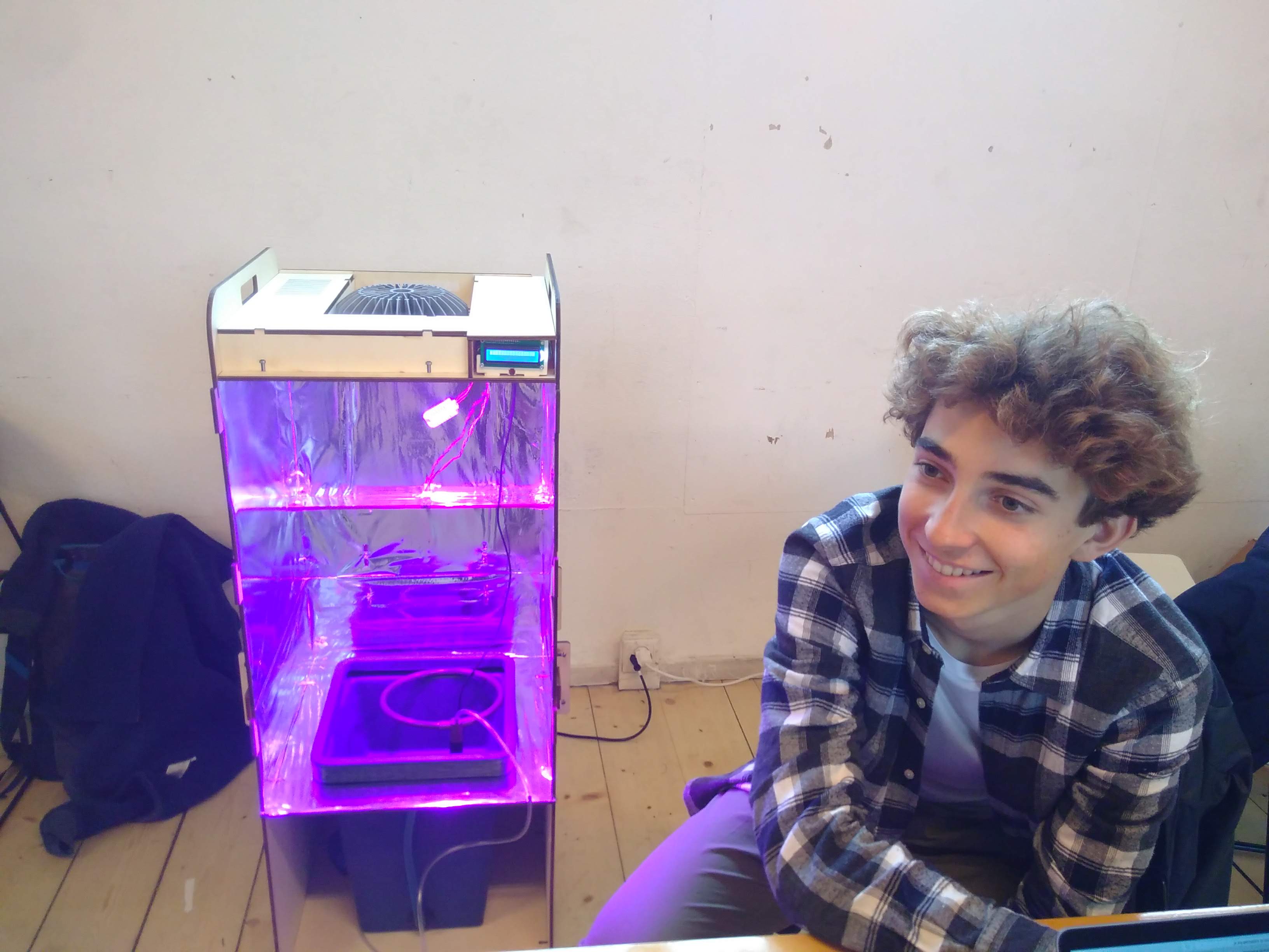
Basil grows well with a 16 hour photoperiod (i.e. 16 hours of light, 8 hours of darkness every day). Therefore, the ON time for all LED lights needs to be set to 06:00 – 22:00 (6 am – 10 pm). The intensity of the LED lights need to be set on: 10% for red, 4% for blue and 2,5% for far red. You can check this in the configuration menu.
Seeds provided by AstroPlant are supplied by a horticultural company for use in the agribusiness. They will have a very high germination rate (80% – 99%, depending on the species). Therefore, it is not be necessary to select the ‘better’ seeds beforehand, and every planted seed can be expected to grow normally.
If the seeds you plan to use are not supplied by a horticultural company for use in agribusiness, it can help your experiment if you make a selection of the ‘better’ seeds before planting. Seed characteristics differ a lot between species, but there are some common traits that can be checked:
If you are using a self-selected species or cultivar, check to see if the species you wish to grow requires a period of vernalisation (cold storage). This is commonly noted on industry supplied packages, as it has a large impact on the germination rate and germination time.
Before starting the experiment, it is crucial to sterilise the seeds. Especially seeds from non-industry sources often have spores of pathogens on them, that will contaminate the experiment right from the start.
Due to the rough matrix of the clay pebbles, the basil seeds need to be germinated outside of the kit. It is best to prepare 2 seedlings per kit if the seeds were sent from AstroPlant (for those have 85% germination rate). If you have acquired your own basil seeds, it is best to prepare 5 seedlings per kit, as they will have a lower germination rate. This way, you will certainly have a viable seedling to start the experiment with. Place the seeds with wet filter paper in a petri dish or small tube. After 8-12 days in the dark, they will have germinated.
Make sure the seeds stay sufficiently wet throughout those 8-12 days.
Check daily to see if the seeds have germinated and both the radicle (first part of the root) and the hypocotyl (first part of the stem) are visible. If this is the case, you can begin planting.
If you germinated seeds fall through the pebbles or fail to grow properly, you can instead grow your seedling on the filter paper until the first two true leaves are 0,5 cm or longer (see 4B; figure 5). After this, the plant should be sufficiently sturdy to find footing among the clay pebbles inside the AstroPlant kit. Because the roots will be larger, you need to handle the seedlings with great care!
If you keep growing the seedlings on the filter paper longer than just after emergence of the radicle and hypocotyl, do not forget to mention this in your manual measurements file (with the amount of days).
Basil is a bushy herb with fast growth. Because of this, and the cut-and-come-again harvesting common for basil, there is no developmental scale available. There are usually only three growth stages indicated; pre-flowering, full flowering and post-flowering. As basil is not grown for the harvest of its seeds or fruits, it is more useful to indicate basil growth in leaf area and fresh mass. Harvesting is usually possible in cycles from 40 days after seeding.
Under conditions better than open field, germination is expected between 8 and 12 days after sowing.[1] The results for basil growth shown below in table 1 and figure 2 were obtained under white LED light, but in soil rather than a hydroponic system. [2]

Usually basil is harvested in cycles, with only some of the leaves being taken each time. This allows the same plant to grow new leaves again, which is more productive than harvesting the entire plant only once. However, the AstroPlant experiments are focused on plant growth, not optimal production strategy. To get the best information on how basil plants grow in an environment, they need to grow for six weeks after germination. Only if the basil plants in all AstroPlant kits are grown the same, will we be able to compare them and the influence of their environments.
When growing for six weeks in good conditions, your basil plant will start to flower. Because basil is grown for its leaves, the flowers need to be removed. This process is called ‘pruning’, and prevents the plant from directing resources to flower and seed development. Instead, after pruning, the plant will use those resources to develop more and larger leaves.

When performing the regular manual measurements, check to see if there are small white flowers starting to grow at the top of your basil plant. If you spot them, look from the top down along the main stem for the node with (small) leaves closest to the flower. A node is the point where a leaf or branch is attached to the main stem. Then, use scissors to cut the main stem 0,5 cm above this node.

Students will make automatic and manual measures to share with the ESA scientists and the other teams.
The goal of the AstroPlant experiments is to obtain an accurate and comprehensive dataset of how plants grow under different environmental conditions. Two types of measurements make up this dataset: automatic measurements and manual measurements. The automatic measurements are made by the various sensors in the AstroPlant kit and can be seen on the dashboard. While the data transfer is under development, we will ask you to send us your dashboard link so we can download the automatic measurement data you have collected and stored.
Manual measurements need to be conducted regularly during growth, and after harvest.
It is important to schedule the measuring of plant growth. This ensures a steady stream of data over time. Especially when environmental conditions change (for example, the mean temperature), measurements need to have short intervals in between.
The vegetative phase of plant growth lasts until the first flower, at which point the reproductive phase starts. Measurement intervals should be shorter during reproductive growth, but this is no issue when growing basil. After all, basil is not grown for its flowers or fruits. Therefore, the measurement intervals can be kept at two to three times a week during the whole duration of the experiment.
For now, all data from the manual measurements needs to be collected in the Excel file ‘Measurements Basil (user name)’.
Be sure to always wash your hands before opening the kit to take measurements.
Two to three times a week, you need to measure:
Branch number: The number of branches of your plant does not include the stem itself. It also does not include the petioles of the leaves. The petiole is the small connection between the leaf and the stem or branch, as seen in the bottom left of figure 6.
Leaf number: When counting the leaf number, count all leaves that are more than 5 mm long. Do not count the two cotyledons (as indicated in figure 5 by the red arrows). Try not to touch the leaves too much during measurements, to reduce the chance of contamination. Also, plants are able to sense touch and might change their development if you touch them regularly in the same way.

Leaf area: Measure the length and width of three developed leaves and enter the average length and width in the manual measurements file. The leaf area is difficult to measure by hand, and for bushy herbs such as basil also difficult to measure accurately by camera. Luckily, a good approximation can be made using the length and width of the leaves. If you enter these values in the excel sheet for manual measurement, a calculation for the leaf area is automatically made. When measuring the length and width, you measure the broadest part of the leaf for width. It is important that measure the length from the tip down to the base of the leaf, excluding the petiole. This is illustrated in figure 6 with two blue lines. (The petiole is the small connection between the leaf and the stem or branch, and is not considered part of the leaf. It should therefore not be measured for the leaf area calculation. In figure 6, it is marked with a red oval.)

Figure 6. Leaf area measurement of a true basil leaf. The red oval indicates the petiole, which should not be measured. Based on the blue length (L) and width (W), the calculation of basil leaf area (LA) is as follows: LA = 0,209 (L2 + W2) + 0,25 (With R2 = 0.895 and RMSE = 0.794) From: Modeling individual leaf area of basil (Ocimum basilicum) (Mousavi Bazaz et al., 2011).
Stem diameter: When measuring the stem, use a calliper for the diameter as this is more accurate that a ruler. Always measure the diameter at 3 cm above the base (the point where the stem ends and the root begins).
Before measuring the stem length, check for flowers and prune the basil if needed. (See 3A for instructions on pruning.)
Stem length: Measure the stem length from the base up to the highest point of the stem, the apex.
pH: Take the hydroponic kit out of the kit and remove the root compartment briefly. Measure the pH in the water of the nutrient compartment three times and write down the average as your measurement.
Electrical conductivity:Follow the same steps as described above for pH.
You should harvest your basil six weeks after it has germinated, according to the following steps:
The measurements that are made after harvest are following the ‘New handbook for standardised measurement of plant functional traits worldwide’.[3]
Measuring the development and expanse of the root system of the plant is very important to the development of the plant growth model. Often overlooked due to their inaccessibility, roots are critical in enabling the above-ground part of the plant to grow. Changes in their development are indicative for plant health, nutrient acquisition, water access, growth strategy and much more. Still, it is difficult and hugely time-consuming to measure the full root expanse. Therefore, the we will use software to extract data on the root system from scans or photographs. In order to obtain reliable data, it is important to make the best image possible. A scan is preferable, but high quality photographs are also adequate. In either case, follow these steps:
The image analysis software is capable of dealing with a limited amount of root overlap, this is included in its calculation. Still, the data will be better if you were able to somewhat spread out the roots without damaging them.
For now, we ask you to send us the images of the root system for analysis (to [email protected]). There are currently several root phenotyping software packages that we are considering. Therefore, the results from the first experiments will be used to select a standard root analysis software, which may or may not be intuitively useable by the users themselves. You are of course encouraged to also experiment with these different software packages under consideration yourself. These are listed in the appendix (8-D).
For a detailed discussion of the various options in root phenotyping software, see Kuijken and colleagues (2015).[5]
Fresh weight:
Dry weight:
Students will update the current documentation with their suggestions and findings. They will be in contact with the European Space Agency and the other teams to share their datas, results and experiences.
Having trouble? Let us know by completing the form below. We'll do our best to get your issues resolved quickly.
"*" indicates required fields