- Loading…

Learning about the solar system is always fun, but it can be even more fun if it was through a game!
This lesson provides the knowledge about the Solar System Planets by going through a story, where the students [players] are the main characters.
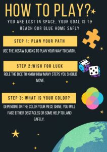
The story starts when an astronauts [the players] got lost in space, and they are trying to go back to their Blue Home, our planet Earth. And on their way back, they are faced with obstacles and some quizzes.

The lesson could be played depending on the number and ages of students, it is adaptable to all age groups and any number of students.
This link below shows a demo of the game:

Preparing for this lesson will require the instructor to have an Arduino to code, printed cards [design attached], and jigsaw pieces [cut with a laser cutter]. To prepare these things here are the materials needed:
Bill of materials:
Preparation:


// SENSOR LIBRARY
#include <Arduino_APDS9960.h>
//ADDRESSABLE RGB LED LIBRARY
#include <Adafruit_NeoPixel.h>
#ifdef __AVR__
#include <avr/power.h> // Required for 16 MHz Adafruit Trinket
#endif
// Which pin on the Arduino is connected to the NeoPixels?
#define PIN 6 // LED PIN
// How many NeoPixels are attached to the Arduino?
#define NUMPIXELS 6 // Popular NeoPixel ring size
Adafruit_NeoPixel pixels(NUMPIXELS, PIN, NEO_GRB + NEO_KHZ800);
#define DELAYVAL 500 // Time (in milliseconds) to pause between pixels
void setup() {
#if defined(__AVR_ATtiny85__) && (F_CPU == 16000000)
clock_prescale_set(clock_div_1);
#endif
// END of Trinket-specific code.
pixels.begin(); // INITIALIZE NeoPixel strip object (REQUIRED)
Serial.begin(9600);
while (!Serial);
if (!APDS.begin()) {
Serial.println("Error initializing APDS-9960 sensor.");
}
pinMode(6, OUTPUT); //LED LIGHT (BASE)
pinMode(9, OUTPUT); // RED
pinMode(10, OUTPUT); //BLUE
pinMode(11, OUTPUT); //GREEN
pinMode(5, OUTPUT); //PUZZER
}
void loop() {
int r, g, b, a;
double rh, bh, gh, cmax, cmin, del, h, hf;
// read the color
APDS.readColor(r, g, b);
// print the values
Serial.print("r = ");
Serial.println(r);
Serial.print("g = ");
Serial.println(g);
Serial.print("b = ");
Serial.println(b);
Serial.println();
// wait a bit before reading again
delay(500);
// LOWER LGB
pixels.clear(); // Set all pixel colors to 'off'
// The first NeoPixel in a strand is #0, second is 1, all the way up
// to the count of pixels minus one.
//for(int i=0; i<NUMPIXELS; i++) { // For each pixel...
// pixels.Color() takes RGB values, from 0,0,0 up to 255,255,255
pixels.setPixelColor(0, pixels.Color(255, 255, 255));
pixels.setPixelColor(2, pixels.Color(255, 255, 255));
pixels.setPixelColor(3, pixels.Color(255, 255, 255));
pixels.setPixelColor(5, pixels.Color(255, 255, 255));
pixels.show(); // Send the updated pixel colors to the hardware.
//delay(DELAYVAL); // Pause before next pass through loop
//}
// SENSOR
// check if a color reading is available
while (! APDS.colorAvailable()) {
delay(1);
}
//find new r,g,b,c,del
//rh=r/255;
// gh=g/255;
//bh=b/255;
cmax= max(r,g);
cmax= max(cmax,b);
cmin=min(r,g);
cmin= min(cmin,b);
del= (cmax-cmin);
// find HUE
if (r>g & r>b)
{h=60*((g-b)/del);}
if (g>r & g>b)
{h= 60*((b-r)/del+2);}
if (b>r & b>g)
{h=60*((r-g)/del+4);}
if (h<0)
{h=h+360;}
Serial.println();
Serial.println(h);
Serial.println();
//GAME SETTINGS
// depending on the value of h, the output led will change colors or the puzzer will turn on
// REFRENCE FOR HUE VALUES FOR THE PIECES OF BLUE HOME GAME:
while ( abs(h-hf) > 5.0)
{
// PINK
if (h>220 & h <360)
{
a= random(1,3);
}
//BLUE
if (h<220 & h >210)
{
a= random(3,4);
}
//BLACK
if (h>180 & h <210)
{
a=random(4,6);
}
//GREEN
if (h<180 & h >140)
{
a =random(1,3);
}
//OFFWHITE
if (h<140 & h >40)
{
a= random(4,8);
}
//YELLOW
if (h<40 & h >0)
{
a =random(3,5);
}
//////////////////
if (a==1)
{
digitalWrite(5, LOW ); // Turn the VIBRATING on
digitalWrite(9, LOW ); // RED
digitalWrite(10, LOW ); // BLUE
digitalWrite(11, HIGH ); //GREEN
}
if (a==2)
{ digitalWrite(5, LOW ); // Turn the VIBRATING on
digitalWrite(9, HIGH ); // RED
digitalWrite(10, LOW ); // BLUE
digitalWrite(11, LOW ); //GREEN
}
if ( a==3)
{
digitalWrite(5, LOW ); // Turn the VIBRATING on
digitalWrite(9, HIGH ); // RED
digitalWrite(10, LOW ); // BLUE
digitalWrite(11, LOW ); //GREEN
}
if (a==4)
{
digitalWrite(5, HIGH ); // Turn the VIBRATING on
digitalWrite(9, LOW ); // RED
digitalWrite(10, LOW ); // BLUE
digitalWrite(11, LOW ); //GREEN
}
if (a==5)
{
digitalWrite(5, LOW ); // Turn the VIBRATING on
digitalWrite(9, HIGH ); // RED
digitalWrite(10, HIGH ); // BLUE
digitalWrite(11, LOW ); //GREEN
}
if (a==6)
{
digitalWrite(5, HIGH ); // Turn the VIBRATING on
digitalWrite(9, LOW ); // RED
digitalWrite(10, HIGH ); // BLUE
digitalWrite(11, HIGH ); //GREEN
}
if (a==7)
{
digitalWrite(5, LOW ); // Turn the VIBRATING on
digitalWrite(9, LOW ); // RED
digitalWrite(10, HIGH ); // BLUE
digitalWrite(11, LOW ); //GREEN
}
hf = h;
}
Serial.print("hf = ");
Serial.println(hf);
Serial.println();
}
 LED stripes in the bottom of the piece.
 RGB LED inside the astronaut’s head, covered with the diffusive paper.
 Vibrating mini inside the astronaut’s body.
** NOTE: Using the electronic pieces and the code will make the game more interactive and fun. However, the game could be played just by having the jigsaw pieces, the printed game cards, and pieces to play with.
Check What you'll need to know all the preparation needed to make the game.
The instructor needs to prepare the game, the cards, the pieces, and the printing and cutting so all the pieces are ready for the students to start with the next step!
This step is the beginning of the lesson. you will be telling the students the story behind the game.
The story telling:
A blue dot in this dark space is our goal. A blue beautiful, shiny dot that we dream of reaching one day. It was once the land that we built, but now we are lost in space. The longing for our Blue Home reached its maximum. We were all just so happy to find a spacecraft that can take us back to our home, Earth. However, the road is not as clear as one can with. It is filled with obstacles that we need to face. Those obstacles require us to know more about our neighboring, the planets that are on our way back. But our faith is strong, and our determination will lead us back, we are sure.
In this step, the path to get back to Earth is planned.

** An example of a simple short path.
Wish for luck! In this step, the first player rolls the dice and move their piece!
Move your piece [Astronaut] the number of steps that the dice lands on. This step is a pure luck!


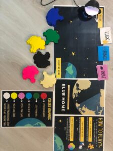
In this step you will see different colors!
* If you went with the interactive game with the electronic and codes:
* If you went with the game with cards and jigsaw pieces only:
** The picture below shows the meaning of each color, and what is your next move!

If you landed on one of those colors, it is learning time!
The cards are in the use now:
 BLUE
BLUE
– you will notice that the blue cards are RING, which is a call received that has an interesting fact about the solar system planets and its moons. Those facts are in the form of an obstacle that will either help you move forward or backward.
 PINK
PINK
– The pink cards are QUIZ, which is a question that has the answer written upside down in the bottom. Make sure that the instructor is the one reading it! If the quiz is answered correctly, the player can move two steps forward.
 YELLOW
– The yellow cards are LUCK, but who says that all luck is a good luck? you might get a card that will be a bad luck for you so wish for good luck!
Each player get the chance to play once in each round, so if you moved forward or backward, you can ignore the new color that your head is shining.
The winner of the game is the one who reaches the Blue Home first!
Having trouble? Let us know by completing the form below. We'll do our best to get your issues resolved quickly.
"*" indicates required fields