- Loading…

Overview
How It Works
Learning Outcomes (Grades 7–9 Developers)
Students gain hands-on experience in:
Teacher Involvement
Inclusive Design
Impact


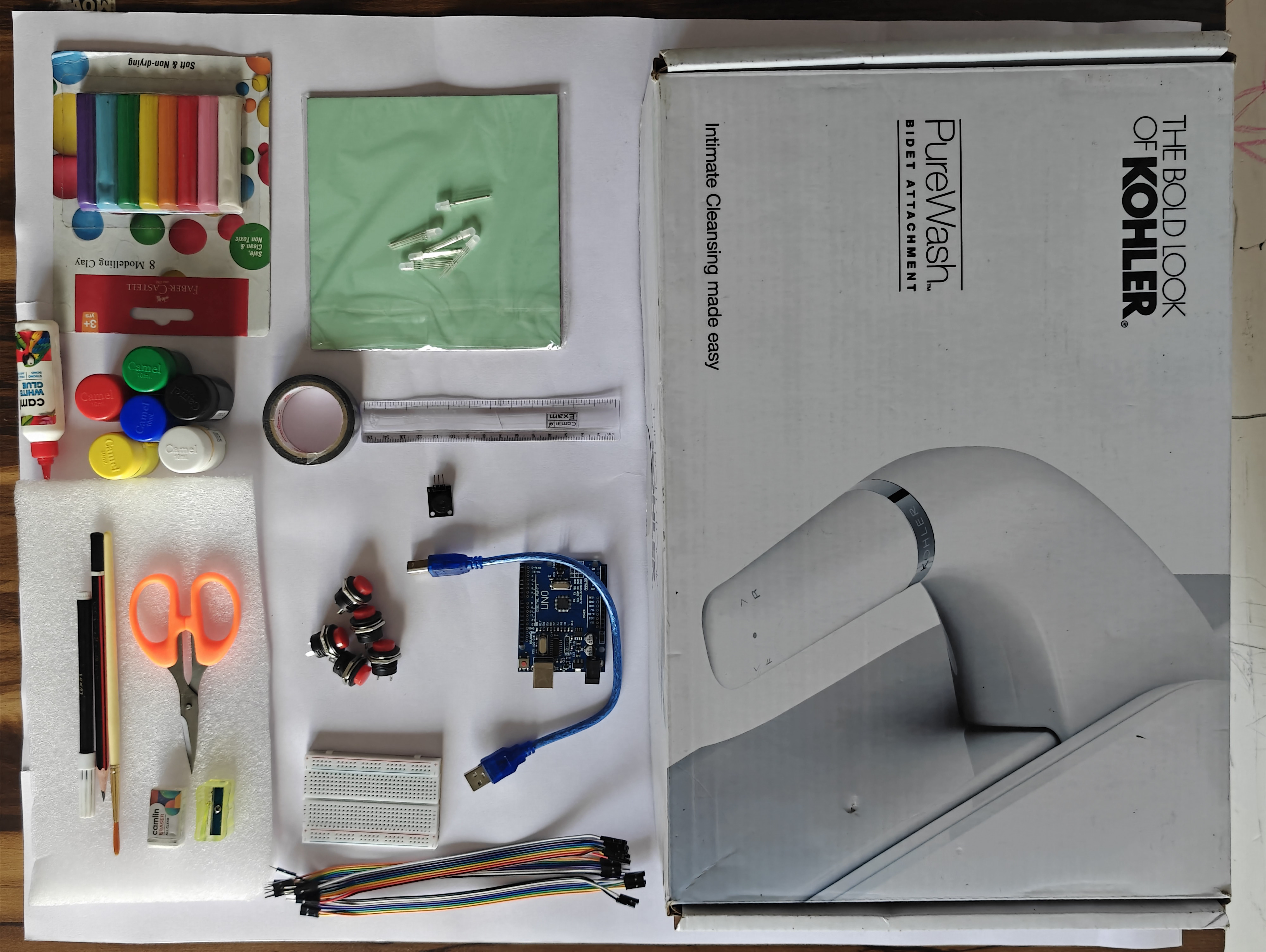
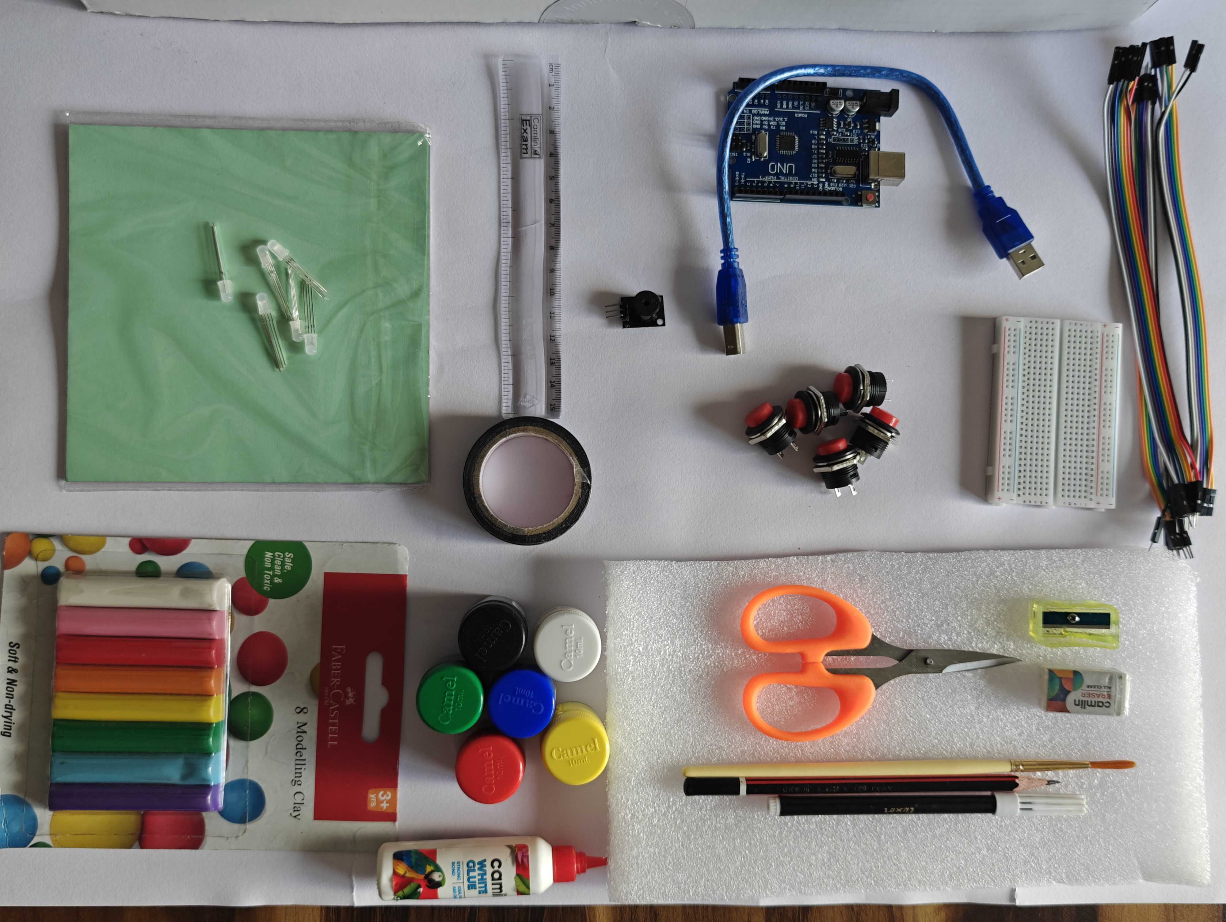
Tools
Design & Structure Materials
Development & Planning
Inclusive Design Additions
By the end of this lesson, students will be able to:
As an electronics engineer and STEM educator, this project reaffirmed my belief that technology education should be purposeful and human-centered. Although I have currently developed the working prototype myself, the true intention is for students to build and refine this Emotion Regulation Breathing Box as a hands-on STEM experience.
This project demonstrates how electronics and programming can be connected to Social Emotional Learning (SEL), inclusion, and real-world problem-solving. It integrates circuit design, coding, sound and light modulation, artistic creativity, and psychological guidance into one meaningful activity.
Designing it also strengthened my focus on inclusive engineering, ensuring the tool supports visually challenged and hearing-impaired students.
I plan to share this framework with other educators so they can guide their students in creating impactful, interdisciplinary STEM projects that combine engineering with empathy and social responsibility.
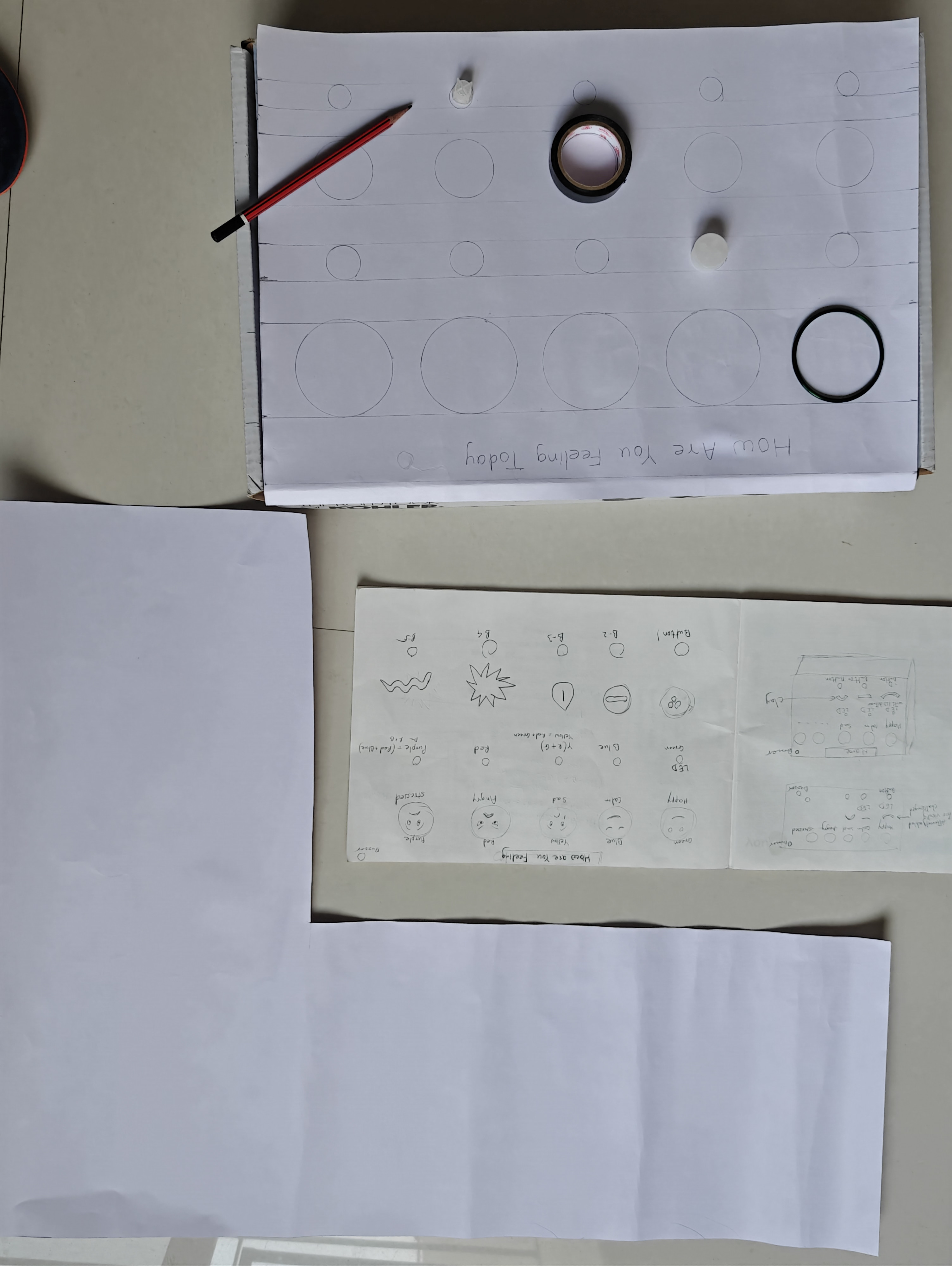
Plan for how our deice will look like
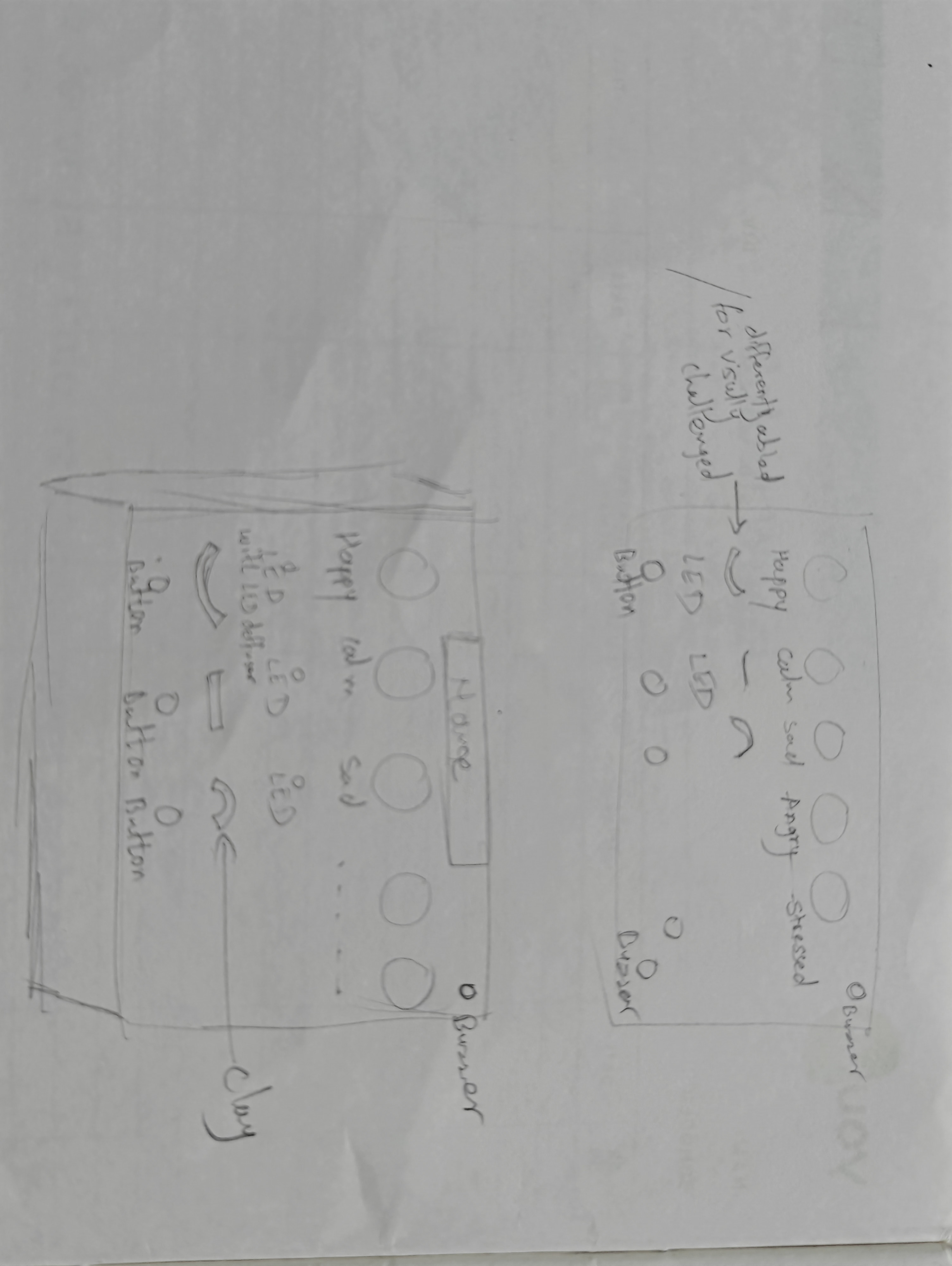
Before starting the physical work, draw a rough design of how your emotion box should look.
Plan where the emojis, buttons, LEDs, and buzzer will be placed. Think about spacing, accessibility, wiring space inside the box, and overall appearance.
This initial sketch helps you visualize the complete system and avoid mistakes during construction.
create rough sketch on box

Select a suitable box (wooden, plastic, or sturdy cardboard) that will hold all electronic components safely.
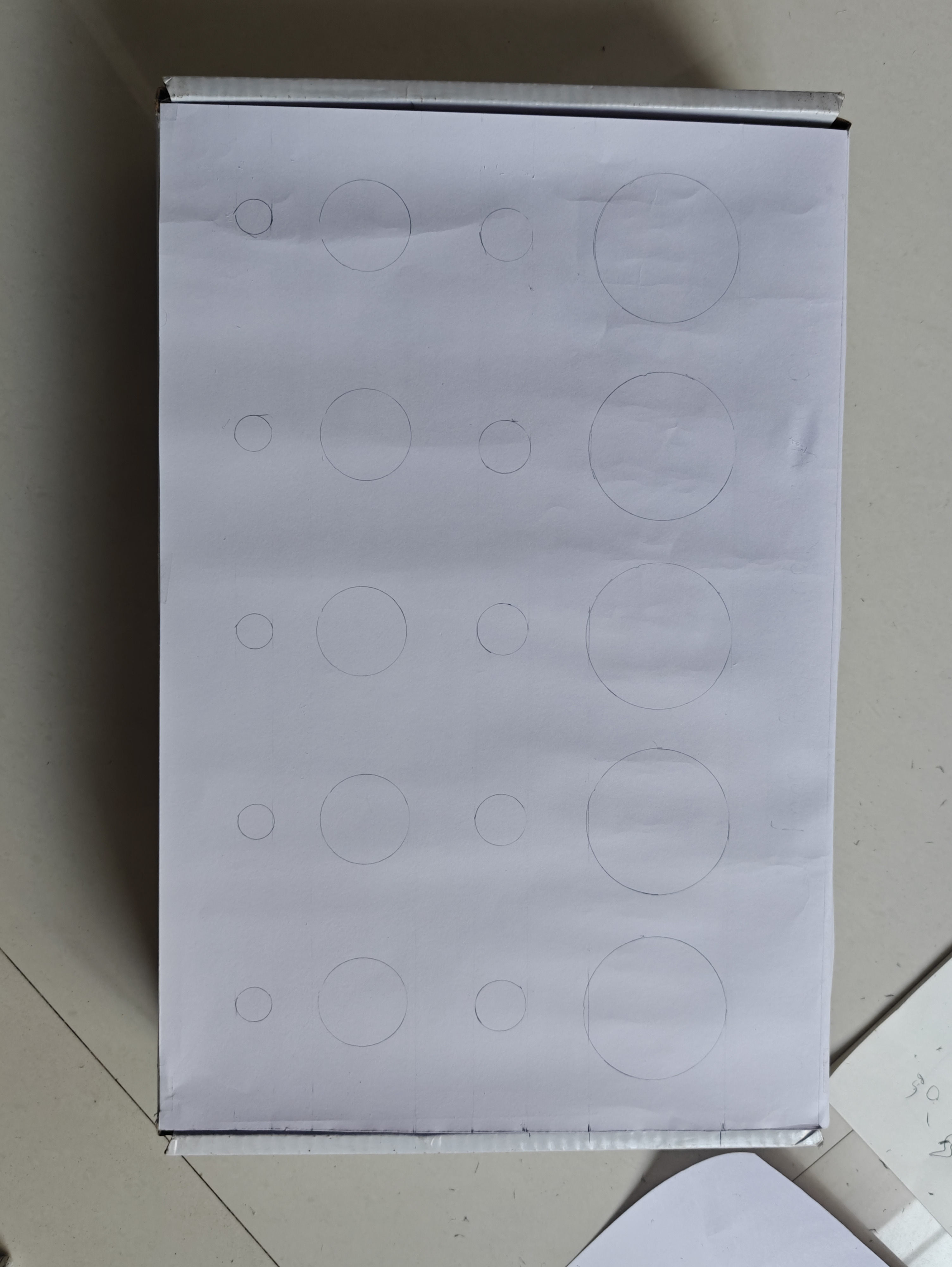
Draw a rough sketch on the top surface to plan the placement of emojis, buttons, and LEDs.
Mark positions carefully to ensure proper spacing, visibility, and easy access before cutting or drilling.
Create a front design template using a card sheet that matches the size of the box surface. This will act as the decorative and functional layout for placing emojis, buttons, and LEDs neatly.

Cut a card sheet exactly the same size as the top surface of the box.
Place it over the box and lightly transfer the reference lines and circle markings made earlier.
Redraw the circles neatly for emojis and button positions.
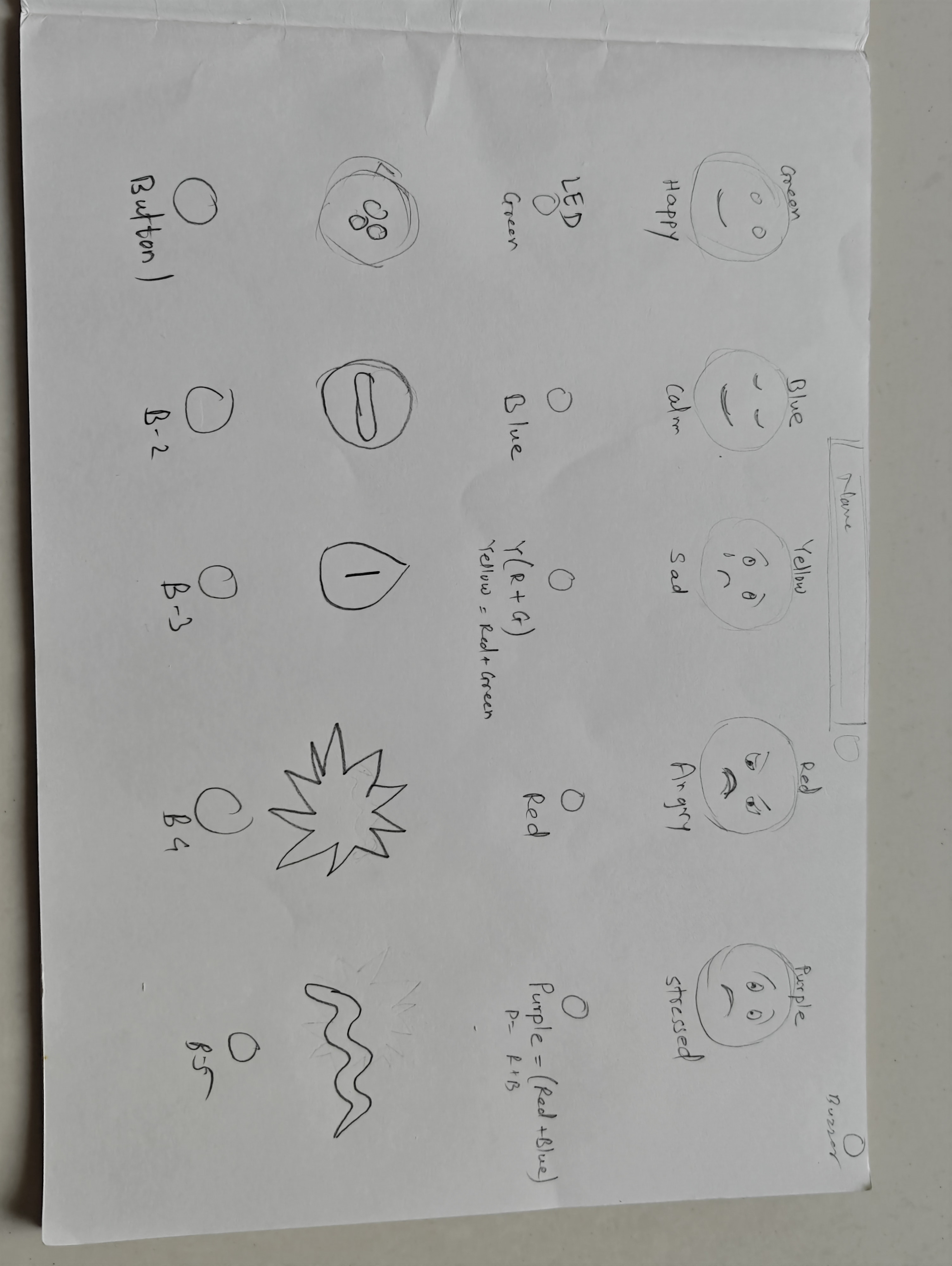
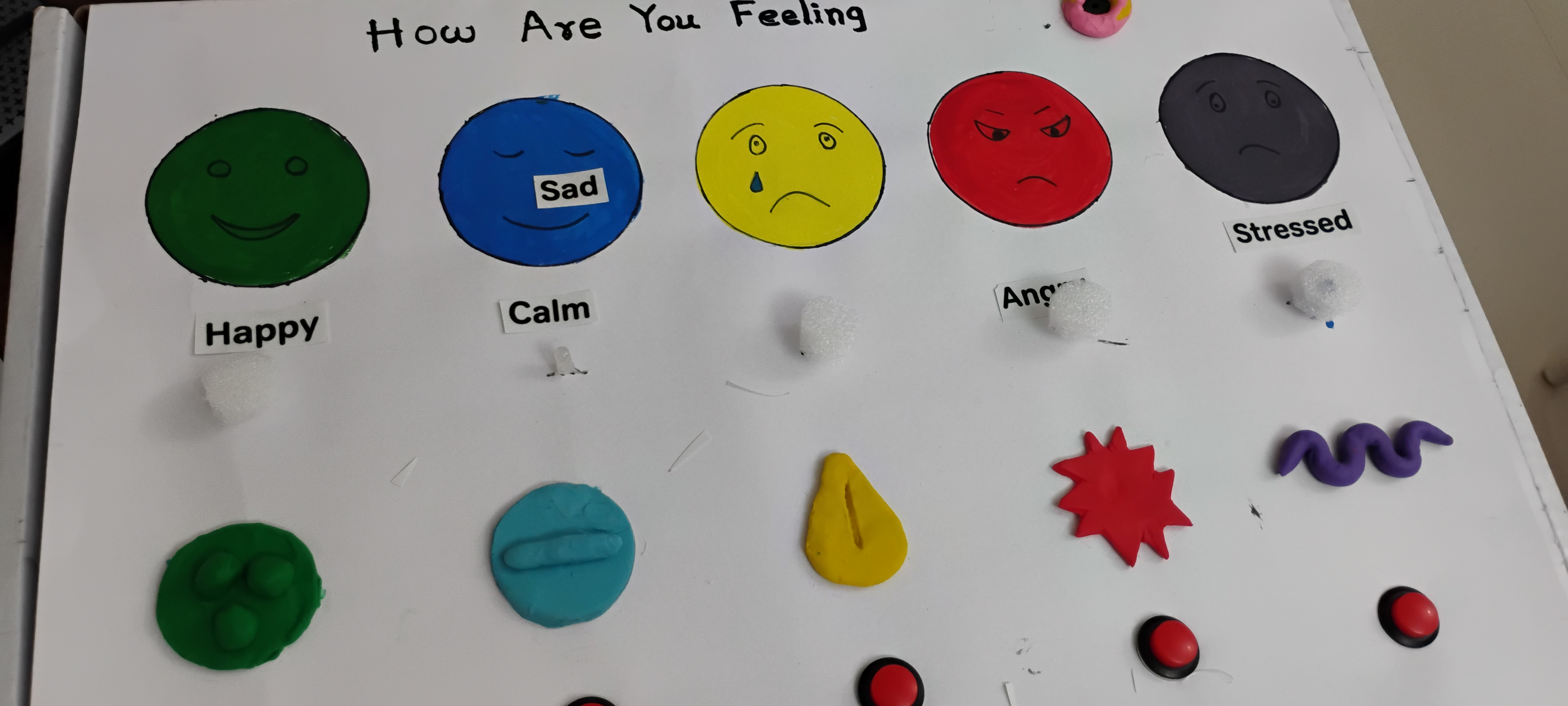
Draw and design the emotion faces and symbols carefully inside the marked circles.
Use a scale for measurements and a compass, circular objects, or a protractor to draw neat circles for the emoji faces and button placements.
Fix the paper with tape on the surface of box
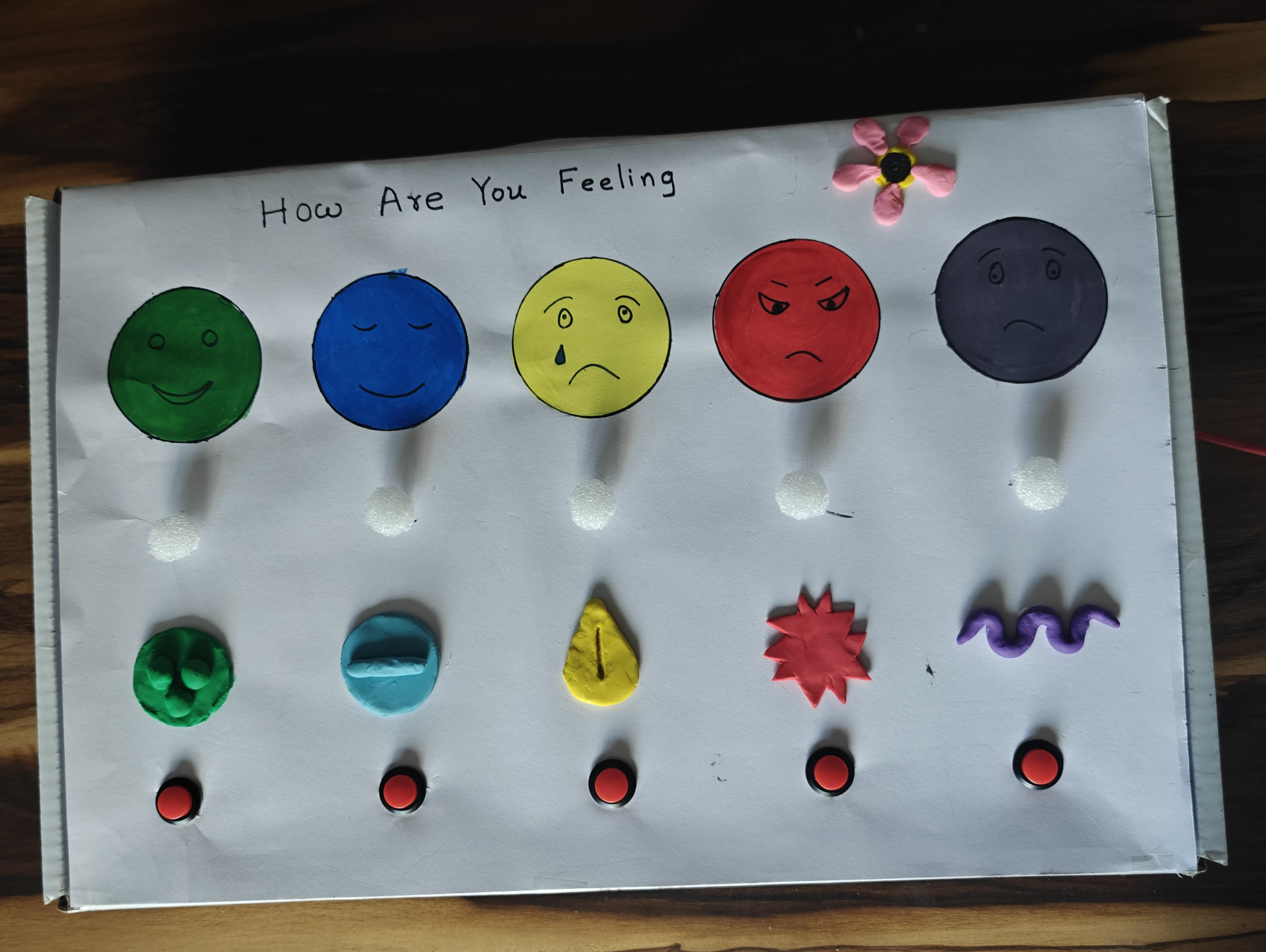
Color the emoji faces before fixing the electronic components. Coloring first allows the artwork to dry properly and prevents damage to the components during painting.
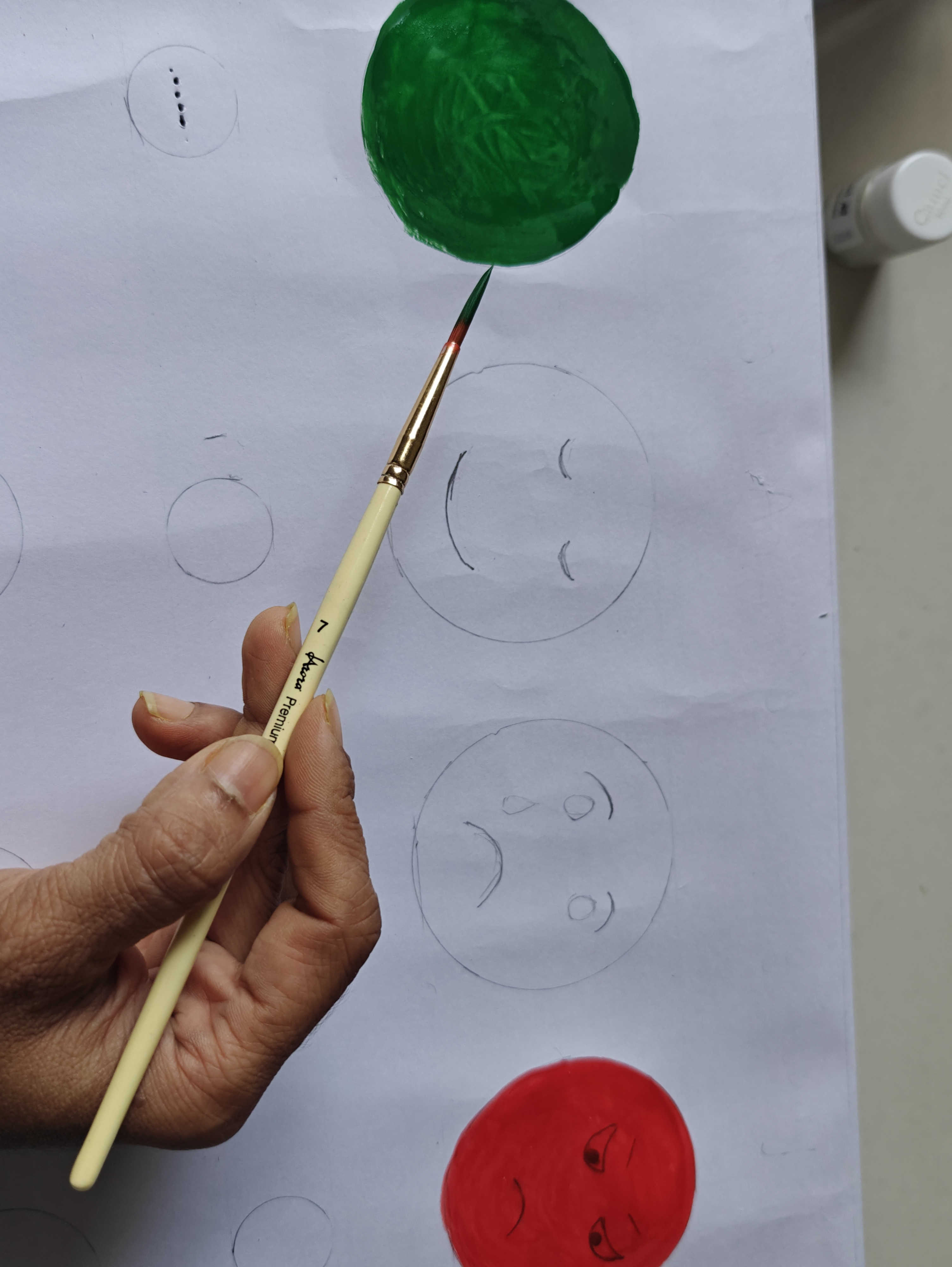
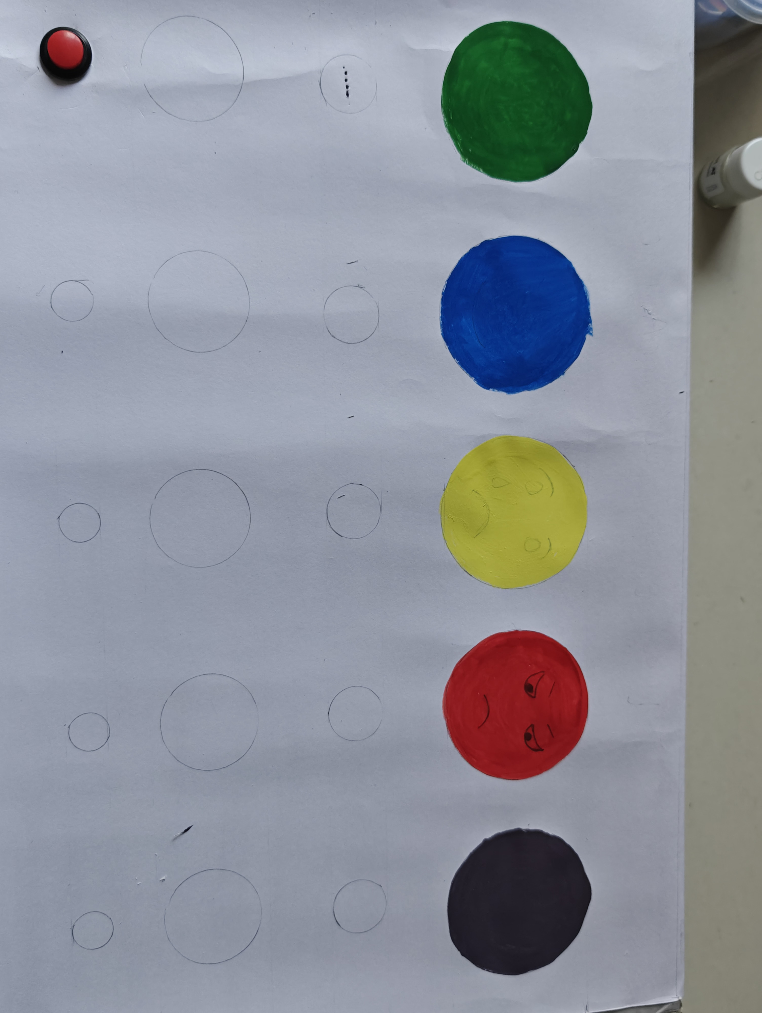
Choose appropriate colors for each emotion. You may use the same color theme or different colors for each emoji.
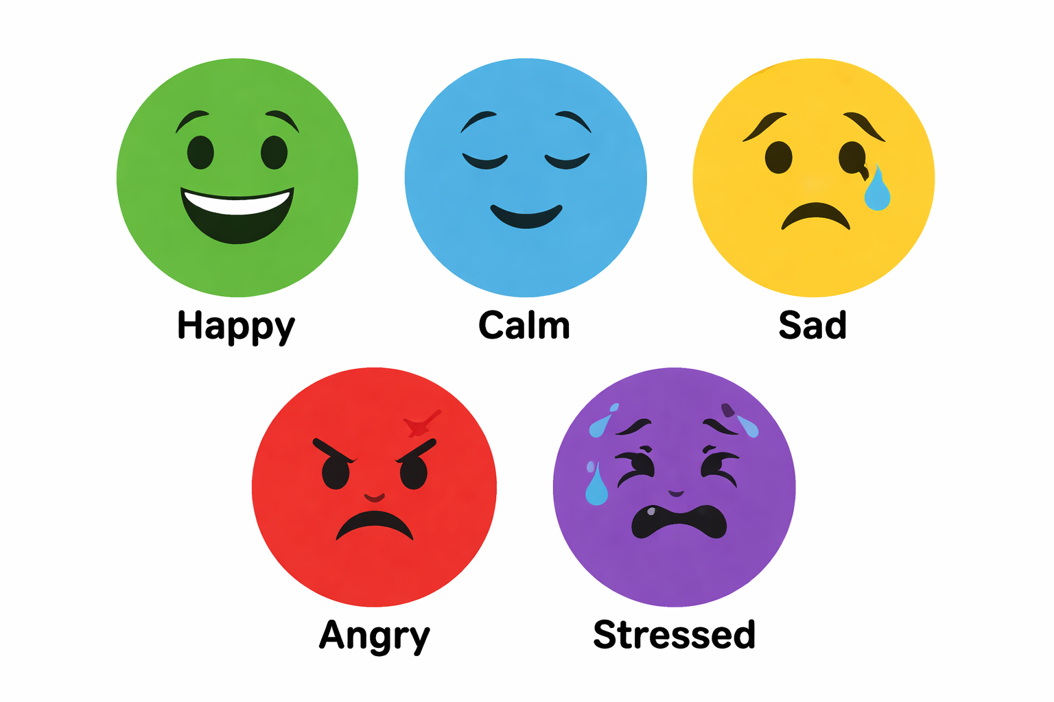
Colors can represent emotions, for example:
Yellow – Happiness, positivity
Blue – Calmness or sadness
Red – Anger or strong emotions
Green – Balance and peace
Purple – Stress or mixed emotions
Carefully color inside the outlines and allow sufficient drying time.
Ensure the sheet is completely dry before cutting holes or fixing LEDs and buttons.
Note:
Although components can be placed earlier, it is better to complete coloring first. This allows the paint to dry while you prepare other materials and prevents smudging or accidental damage during installation.
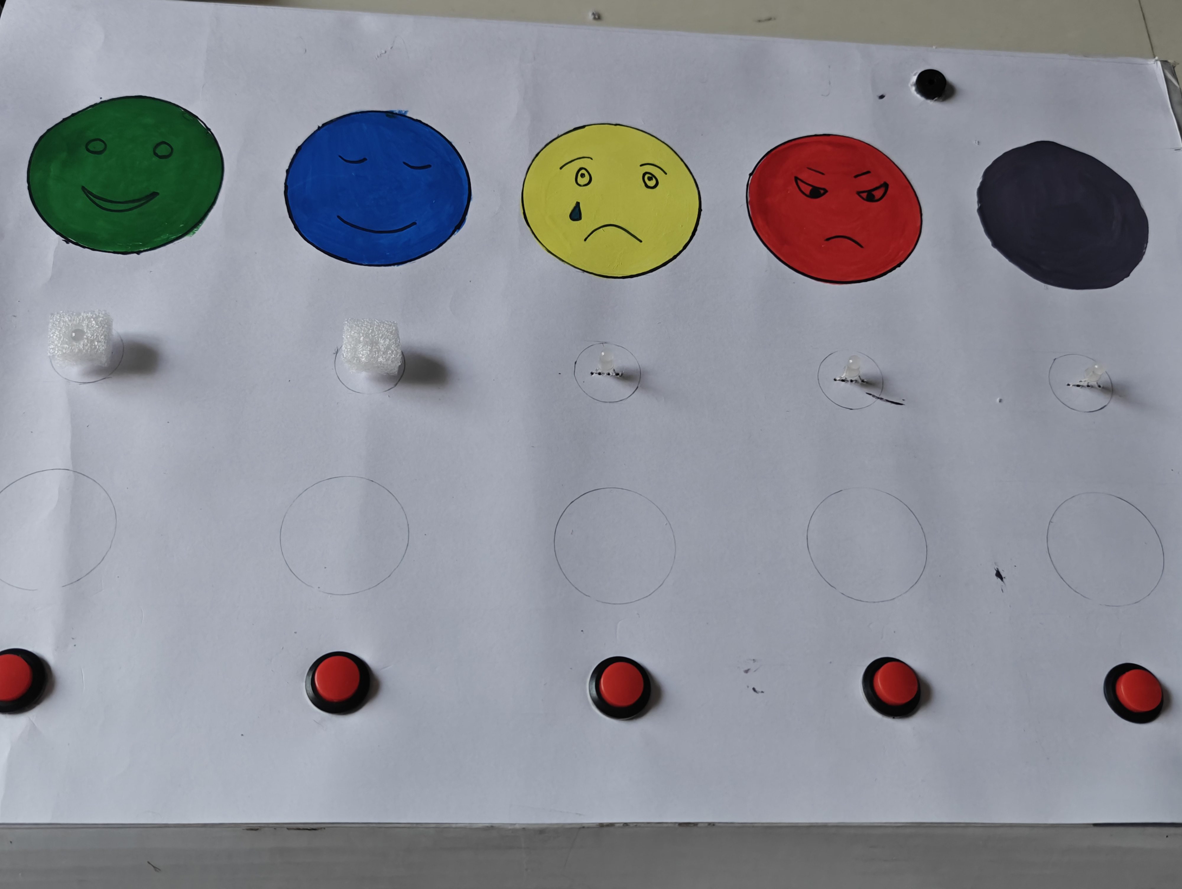
Make precise holes in the card sheet for LEDs, buttons, and the buzzer so that each component fits securely in place.


This step ensures proper alignment and a clean, professional finish.
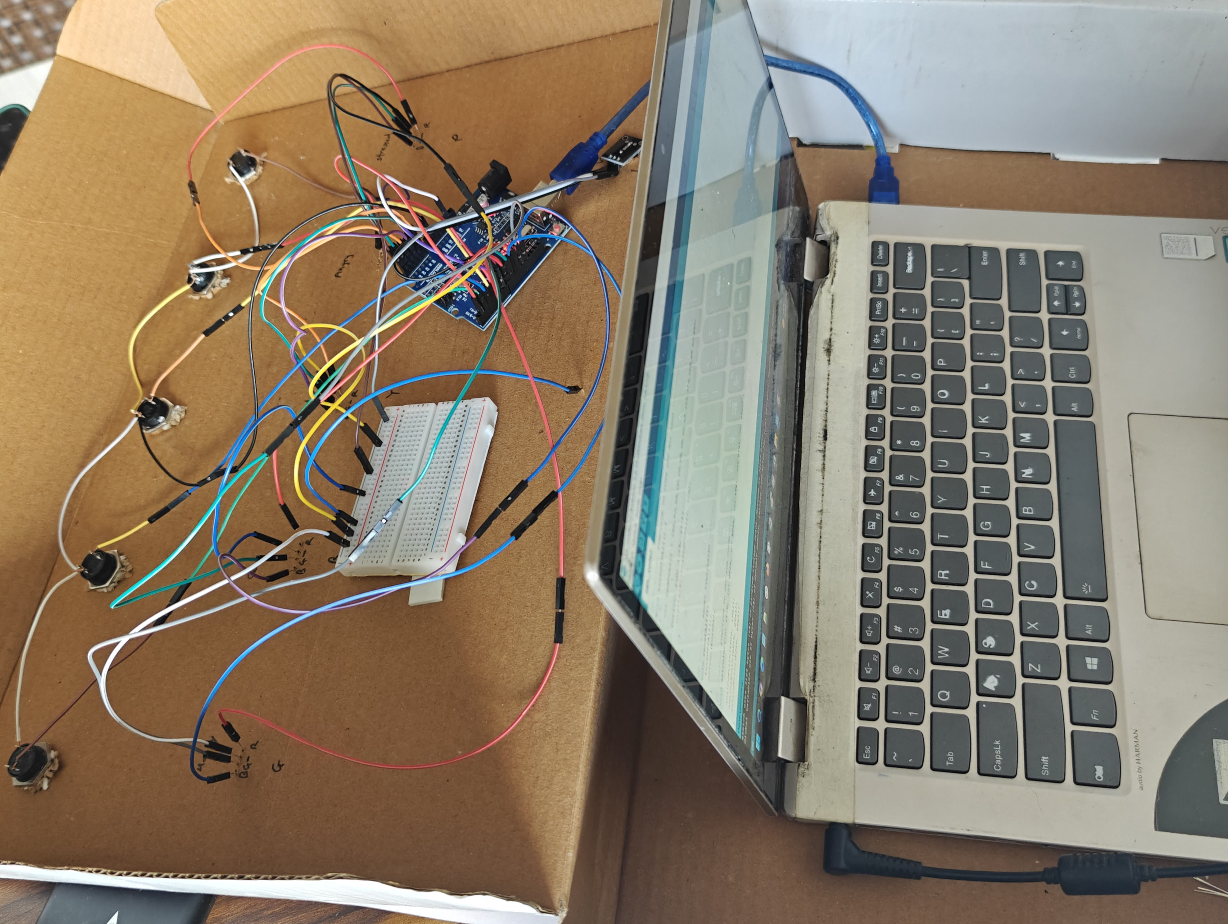
Before making electrical connections or writing the code, define the working logic of the system. Writing the algorithm helps students clearly understand how the system should behave and prevents confusion during wiring and programming.


For each emotion:
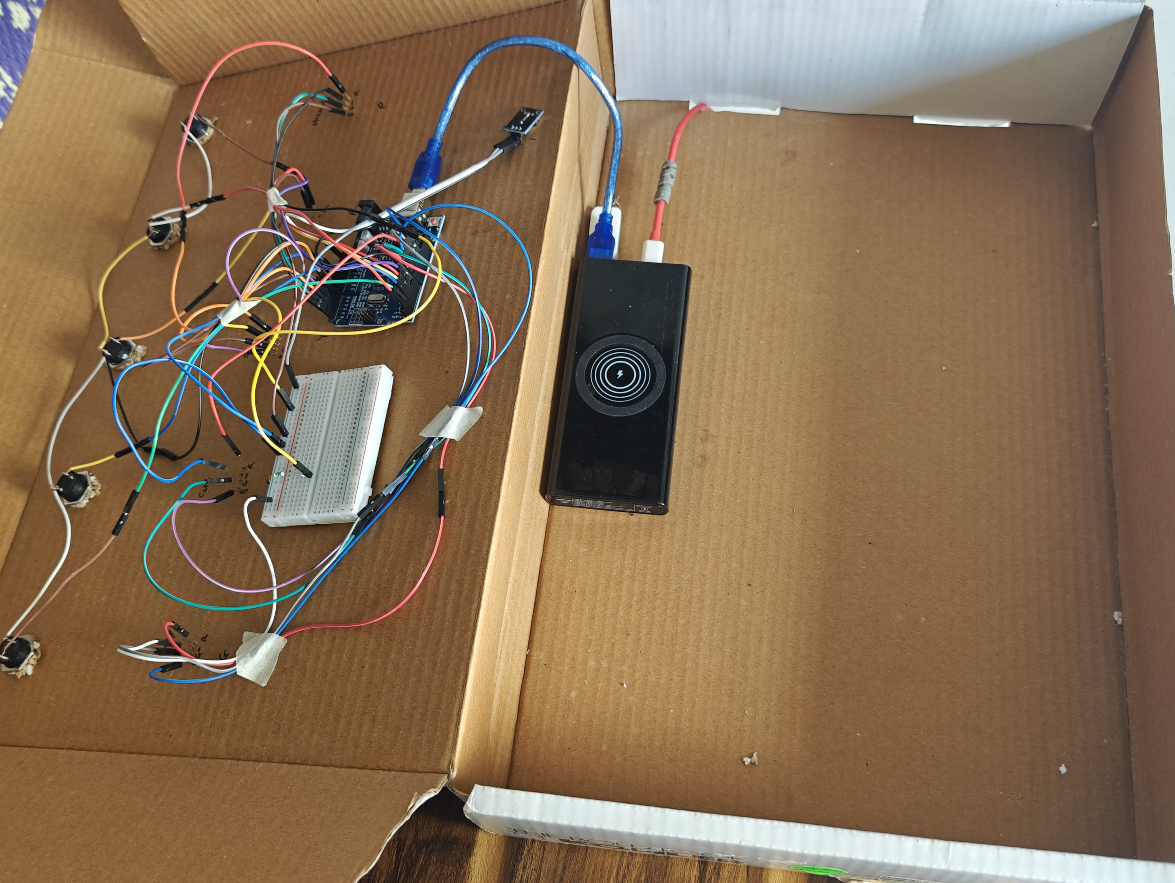
Now connect all LEDs and push buttons to the Arduino according to the circuit plan. Since we are using common cathode LEDs, proper grounding is very important.


Arduino Uno has only 6 PWM pins (3, 5, 6, 9, 10, 11).
Example mapping:
Since PWM pins are limited, I connected Red and Blue pins of the last RGB LED (Purple emotion) together to one PWM pin.
Example:
Upload the final program to the Arduino to control the LEDs, buttons, and buzzer according to the emotion-based breathing patterns.


Add an LED diffuser to soften and spread the light evenly. This makes the breathing effect smoother, easier on the eyes, and more visible for students.
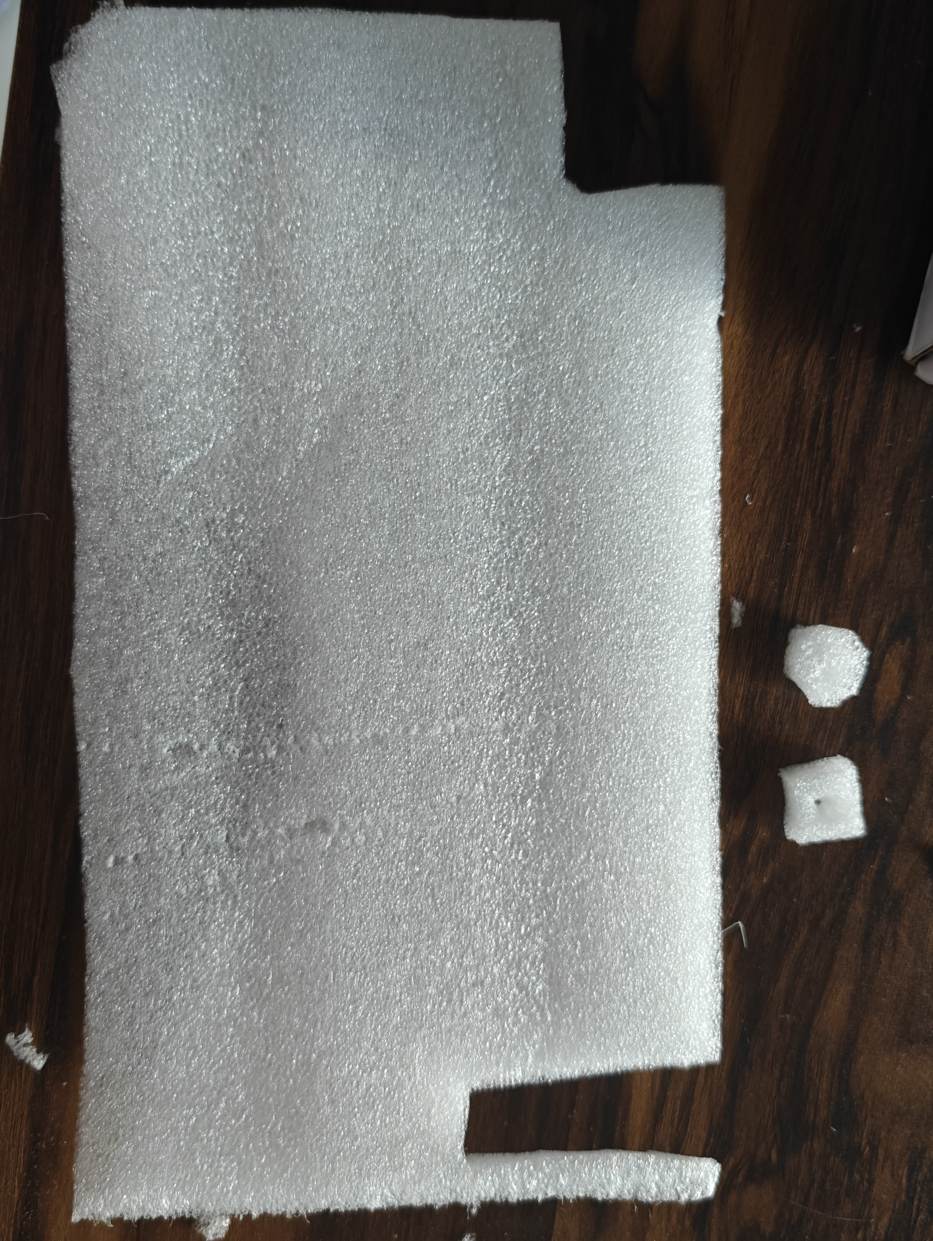
Cut small circular pieces of butter paper, tracing paper,foam sheet, frosted acrylic sheet, or thin white plastic slightly larger than the LED hole.
Place the diffuser material over or in front of the LED opening.
Fix it securely using glue or tape from the inside of the box.
Ensure the diffuser does not block the light completely.
Power the device and check that the light spreads evenly and appears soft.
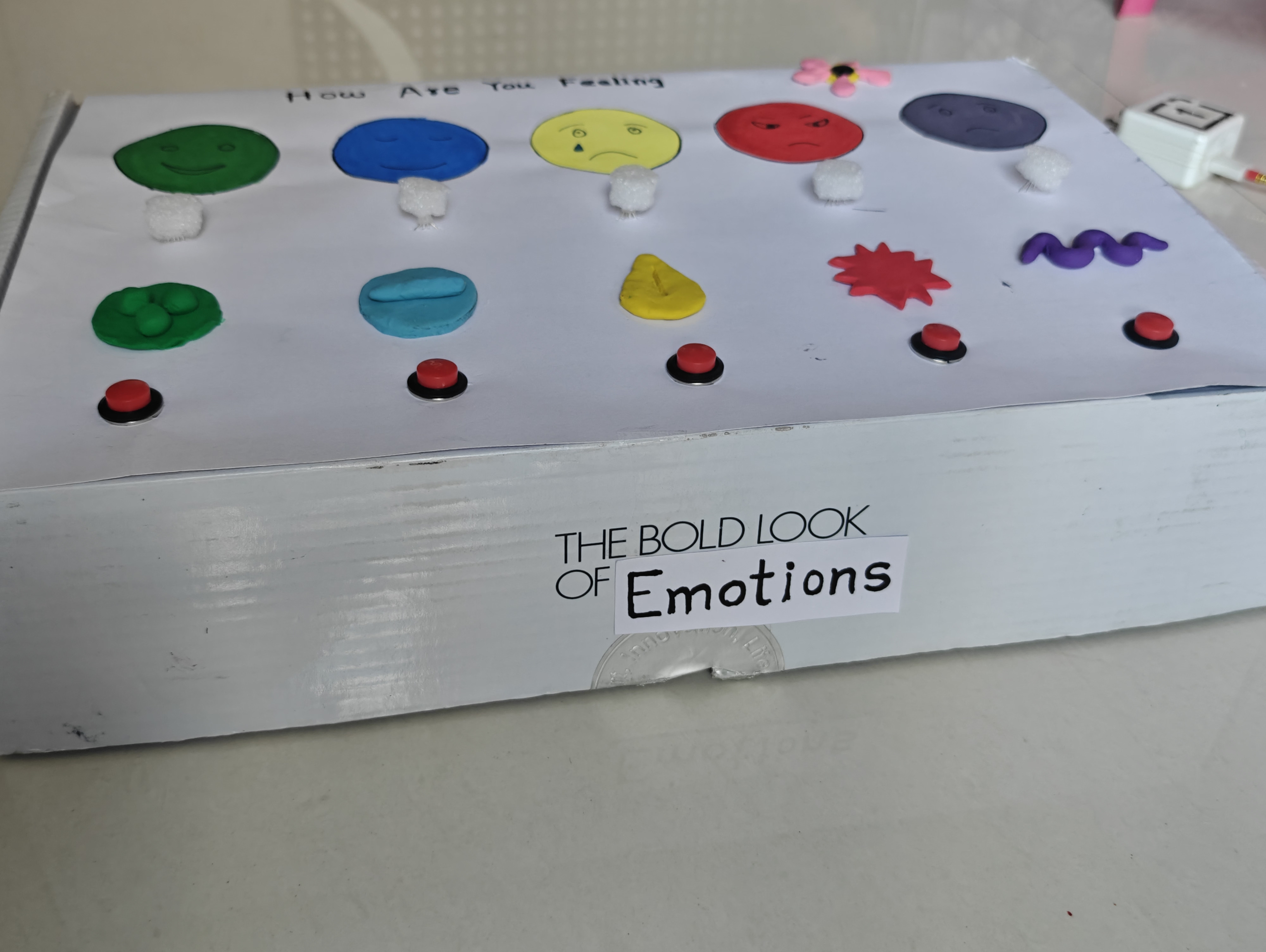
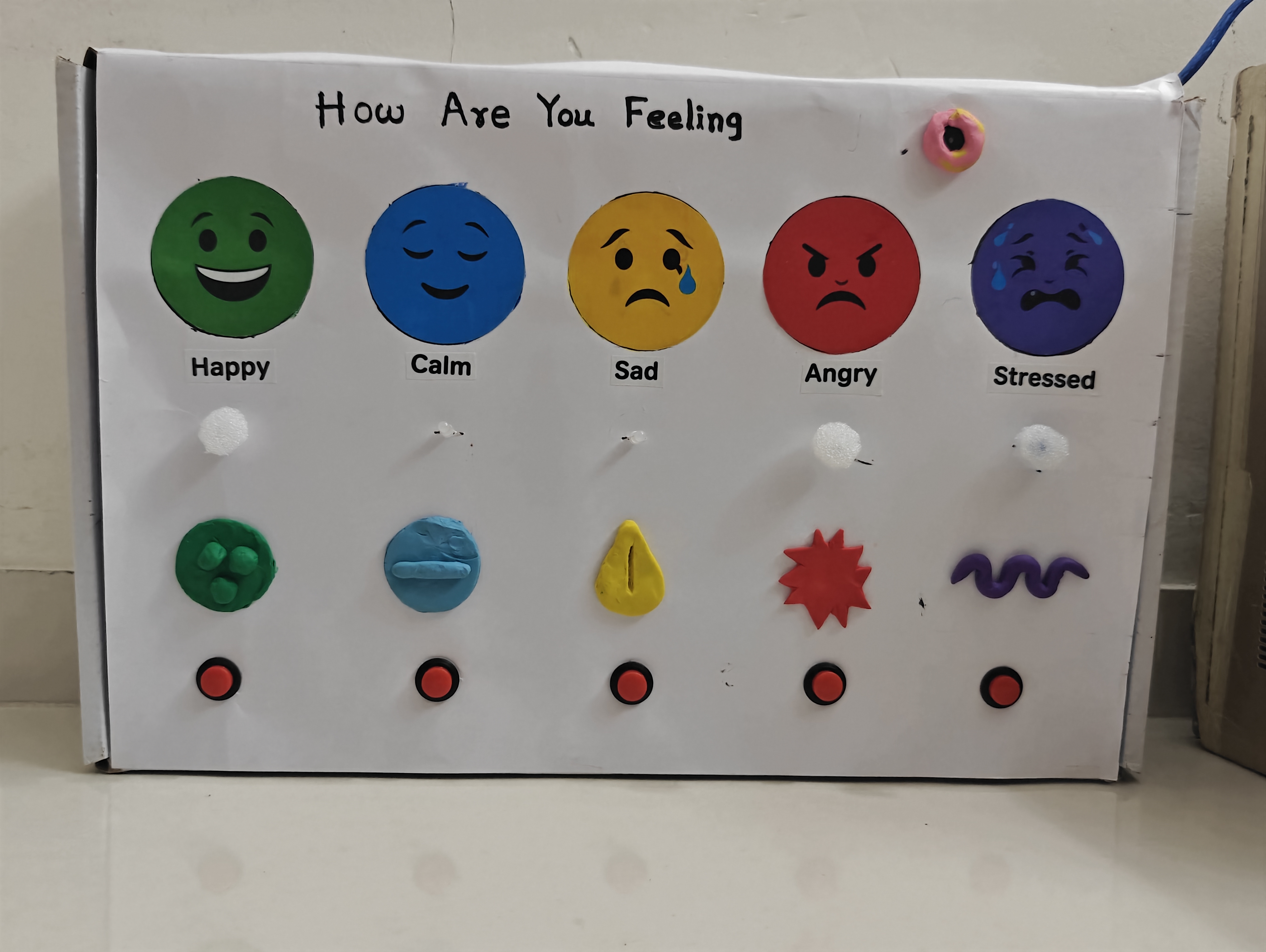
Add raised clay symbols on each emotion to make the box accessible for visually challenged students. These tactile symbols help them identify emotions through touch.

.jpg)


Apply printed emoji stickers to give the Emotion Box a clean, attractive, and professional look.
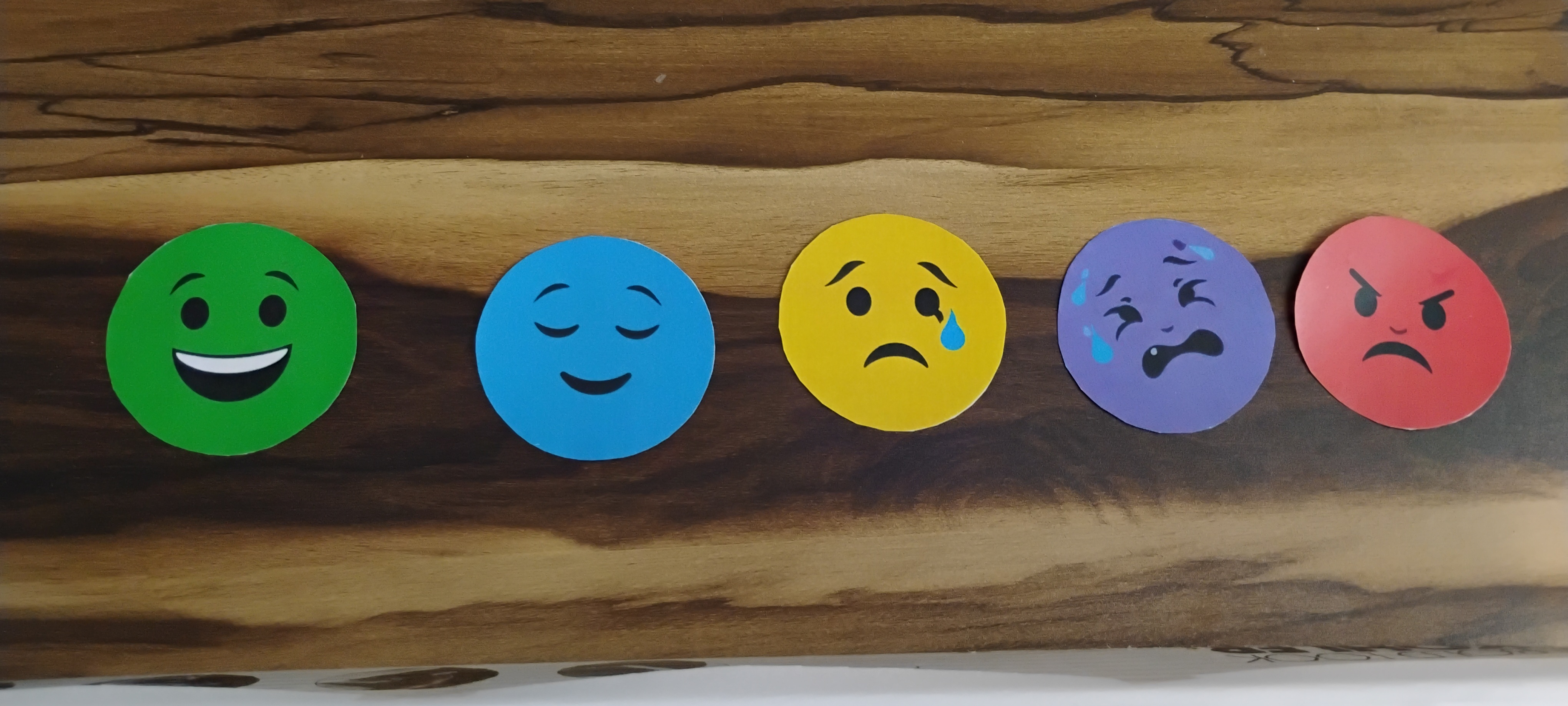
Take a printout of the emoji sticker PDF provided in the attachment
cut it and paste it on the box
Complete the final setup and test the Emotion Box to ensure all components function correctly. At this stage, you may also enhance the appearance using printed emoji stickers instead of painted designs.


Having trouble? Let us know by completing the form below. We'll do our best to get your issues resolved quickly.
"*" indicates required fields