- Loading…

On-site Workshop aims toward building the knowledge of Neuroscience and how thoughts are formed in order to build a prototype able to read the signals coming out from the brain to the muscles.
The workshop are going to be delivered in 3 days:
Day 1 –> Solder small component
Day 2 –> Solder Big component
Day 3 –> Test The board

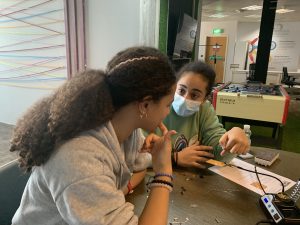
This section, will introduce the participant to the Neuroscience and the formation of thoughts.
1- We will motivate the participant to straighten up their mind in a way to find how we can think and imagine.
2- We will share together our opinion about a quote.

2- Then we will ask them how we are imagining these things.

3- Then we will ask how these thoughts are formed.

4- Thoughts are a chemical release in the brain, which generate an electrical signal in the neurons, This signal will propagate like a wave to thousands of neurons.

5- Explain the neurons as an information messenger uses electrical pulses and chemical signals.

6- Then we will describe the human brain as a complex organ weight up to 3 pounds and are formed out of water and fats.

7- Then we will show them a video about the human brain.

8- Then we will ask them for an example of a human made thing that can mimic the brain.

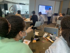
In this section we will show the participant what we will do today and we will show the participant the working principle of the board they are building.
1- We will tell the participant that we will be soldering the board of Muscle shield, so we can read the signals reaches the muscles from the brain.

2- Then we will show a video for the participant to show what the board is capable of.

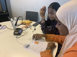
3- Then we will show the needed component to have the board done

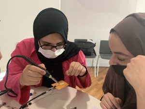
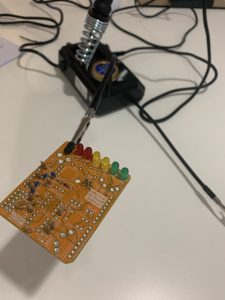
In this section, we will show the step-by-step to solder the board.

1- We will guide the participant on how they can solder.

2- Then we will start preparing the board for the soldering process by knowing the direction of the board.
3- Then we will introduce the component we have to install and solder, to classify each type a side.
4- Then we will start with the diode, and we will solder it.


5- Then we will ask the participant to recheck their soldering, so they make sure the diode is firmly installed and connected.
6- Then we will start installing the capacitors, In this kit we have two types of capacitors blue capacitor and brown capacitors.

7- Then we will install the brown capacitors.


8- Then we will show the board after installing these component, and we need to make sure that all the component are connected.

9- At this point we have finalized all the capacitors and the only diode.
10- Now we need to install all the resistors of the kit, But the resistors are going to be installed in a (U) Shape, so we have to bend the resistor before it’s installed on the board.

11- We have to make sure that all the resistors are the correct value in the correct place.

12- This how the board should look like after the resistors being installed.

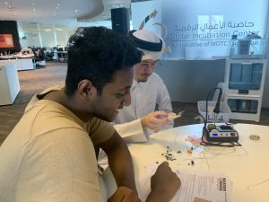
In this section we will show the installation of the big component on the board and how to isolate the board to be connected with the Arduino as a shield.

1- We will start with showing the component we want to install and solder.
2- The first component are going to be the 3.5 mm jacks for the input signal and the output signal.


3- Then we have to install all the remaining component and solder them (relay, LED’s, switches, push button, and the IC’s Holders).
4- We have to make sure that all the pins installed are in the right position and not tilted, so they go through the pin of the Arduino.

5- Then we have to isolate the back side of the shield using electric tape to avoid the contact with the Arduino metal head.

6- Then we will connect the shield with the Arduino.


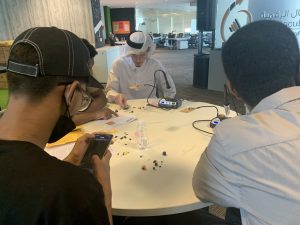
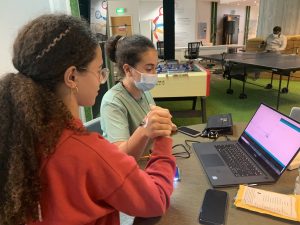
In this section we will test the shield with the Arduino and also we will visualize the data on the Arduino IDE.

1- It’s necessary to recap all the information we had in the previous days.

2- It’s Important also to ask the participant if they have any questions regarding what they have been through in the previous days.

3- Then we will ask the participant the needed question.


4- Then we will ask about the PCB and what it stands for.


5- Then we will show the participant what we will do, and we will show them a video about the capability of the shield.


In this section we will upload the code to the microcontroller and we will visualize the data coming from the device.

1- The first step is to make sure that the shield and the board are connected.
2- Then we will open the provided code.

3- Then we have to install the library of the I2C LCD.


4- Then we will connect the Arduino to the computer, and we will prepare the setting to upload the code to the Arduino.

5- Now we will unplug the Arduino from the computer, and we will connect the LCD with the device.

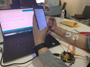
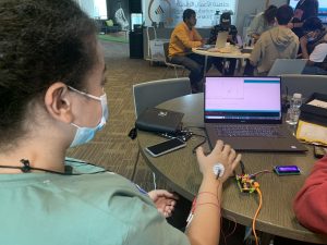
6- Then we will connect the Electrode signals pads on the wrest.

7- Then we will plug the Signals wires with the pads and the Arduino to the computer to be powered up.

8- Then if we want top visualize the data, we have to go to the Arduino IDE and open the serial monitor or the Serial Plotter.

9- Serial Monitor

10- Serial Plotter

Note: It’s important to make sure that all the participant have their board firmly soldered and all the part are in the right place.
Also, The board has 2 different moods, so make sure the board at the correct mood through moving the switch right and left.
Having trouble? Let us know by completing the form below. We'll do our best to get your issues resolved quickly.
"*" indicates required fields