Adding Integers on Scratch Number Lines - SCOPES Digital Fabrication

Lesson Details

Subjects
Age Ranges
Standards
7.NS.A1, Fab-Safety.1, Fab-Programming.1, Fab-Electronics.1, Fab-Fabrication.1, Fab-Design.1, Fab-Safety.2, Fab-Programming.2, Fab-Electronics.2, Fab-Fabrication.2, Fab-Programming.3, Fab-Electronics.3
Author
Additional Contributors

You need to login or register to bookmark/favorite this content.

Author

Tyler Andrade
K-12 teacher

Summary

This lesson will help support students in their conceptual understanding of how to utilize a number line to add integers while using technology.


Students will use a vinyl cutter, Scratch program, and Makey Makey to create a learning tool for themselves to support their understanding of how to add integers using a number line. Teachers can use problem sets of their choosing to supplement this learning tool.

What You'll Need

  • Makey Makey
  • Roland Vinyl Cutter
  • Copper Tape Roll 6’
  • Scratch Program
  • Cut Studio Program
  • Cardboard Rectangle (4.5in x 3.5in)
  • Provided Controller Template jpg
  • Provided Number line jpg
  • Computer
  • Scissors
  • Transfer Paper


The Instructions

Using the Roland Vinyl Cutter & Cut Studio

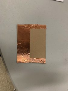
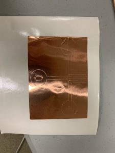
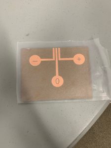
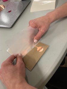
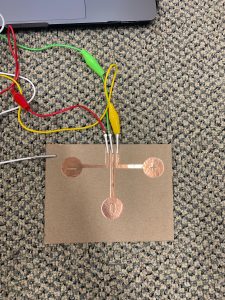
Students will learn, understand, and know how to prepare and use the Roland Vinyl Cutter to create remote control components. Students will utilize a pre-made template for their own individual remote control.

Preparing the Roland Vinyl Cutter

  1. Prepare the vinyl cutter by clicking the “Menu” button two times.
  2. After clicking it twice, a message will appear that says “Unsetup.” Click the “Enter” button when you see this message.
  3. On the left side of the cutter, push the lever down. This will cause the plungers on the machine to lift up.
  4. Feed the copper tape through the cutter beginning on the left side of the machine.
  5. Line the two rollers up to fit the width of the copper tape roll. These need to be within two of the white markers on the front of the machine. These rollers can be easily moved left and right from the back of the machine.
  6. Once the rollers have been positioned, pull the lever on the left side of the machine up to lower the plungers.
  7. Once the plungers are down, a message will appear on the screen saying “Roll.” When this message appears, click the “Enter” button.
  8. The copper tape needs to cover the front sensors. To cover the front sensors, click the down arrow button on the machine and hold it until the sensors have been covered.
  9. Once the sensors have been covered, hold down the “Origin” button to set the origin.
  10. Set “Pen Force” to –2 by moving the dial manually.
  11. Click the “Force” button and make sure the force is set to 90 gf.


Using the Cut Studio Software

  1. Download the jpg template for your remote control. This template will be made available to you by your teacher through his or her preferred platform.
  2. Open the Cut Studio program.
  3. Click on “File” and select “Cutting Setup.”
  4. Under “Change Media Size” click on “Get from Machine.”
  5. Click OK. When that window closes, click OK again.
  6. Click the “Import” icon and import your downloaded jpeg template.
  7. Right click on your image and select “Image Outline.” This can also be done by clicking “Object” and selecting “Image Outline.”
  8. Click “Extract Contour Line,” then click OK.
  9. You may now delete the original image. You will need to select the original to delete it, which may require clicking on it and moving it over to the left or right away from your new image.
  10. Click on your new image and click “Properties.” This will bring you to “Size and Shape.”
  11. Under “Size and Shape,” type in 90 to the right of “Rotate Angle” and then click “Enter.”
  12. Click on the button “Move to Origin.” This can also be done by clicking “Object” and selecting “Move to Origin.”
  13. On the left side of the screen, select the box icon and draw a box around your image.
  14. Select the image and the box.
  15. Again, click on the button “Move to Origin.” This can also be done by clicking “Object” and selecting “Move to Origin.”
  16. Finally, you may cut your image! Click on “Cutting” and select OK.
  17. After Roland finishes cutting on the copper tape, hold the down arrow down to feed the tape away from the cutter until there’s enough space to cut your piece off.
  18. Cut your piece off using scissors. Do not do anything with this until you build your remote.


Preparing Scratch Code

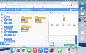
Students will learn and apply coding to maneuver their remote control using the Scratch Program.

Preparing your Scratch Project

  1. Download the jpg image of your number line. This template will be made available to you by your teacher through his or her preferred platform.
  2. Go to scratch.mit.edu in your web browser.
  3. Sign into your account.
  4. Click on “Create” on the top left corner of the screen.
  5. Hover over the “Choose a Backdrop” icon on the bottom right corner of your screen. Select the top icon for “Upload Backdrop.” Upload your downloaded image.
  6. Click on “Convert to Vector” on the bottom left of the screen.
  7. Click on the number line. Drag the corners of the image to fit the square window. Center the number line as best as you can.
  8. On the bottom right of the screen, click the default Sprite, then click the trash can to delete it. 
  9. Now click on the “Choose a Sprite” icon on the bottom right.
  10. Choose the “Lightning” Sprite.
  11. Click on your new Sprite. Change its size from 100 to 80.
  12. Drag your sprite so it hovers over 0 on the number line.
  13. TAKE NOTE of your Sprite’s position. Write down its x and y coordinates.


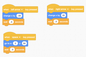
Writing your Scratch Code

  1. Click on the “Events” circle under code, and drag over three separate “when space key pressed.” Do not put them on top of each other.
  2. Click on the “Motion” circle under code, and drag over “change x by 10” and drop under two of your “when space key is pressed” events.
  3. Click on the “Motion” circle under code, and drag over “go to x:# y:#” and drop under your remaining “when space key is pressed” event.
  4. Click on the “Control” circle under code, and drag over “wait 1 second” and drop under all of your events below your blue motion codes.
  5. For your blue motion code “go to x,” type in the coordinates you wrote down earlier for your Sprite.
  6. Below it, change wait 1 second to 0.5 second.
  7. For your blue motion code “change x by,” type in 20 for one and -20 for the other. 
  8. Below them, change wait 1 second to 0.5 second.
  9. On the yellow event code above 20, change “space” from the drop-down menu to “right arrow.”
  10. On the yellow event code above -20, change “space” from the drop-down menu to “left arrow.”
  11. Your code is now completed to use with your Makey Makey.


Building the Remote Control Circuit

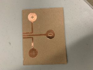
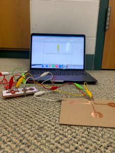
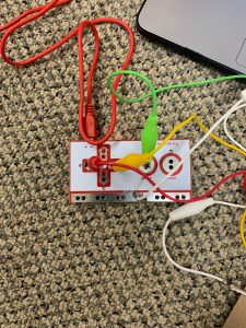
Students will use the Makey Makey kit along with the Scratch Program and knowledge of coding to build their remote control in order to move their icon along the number line.

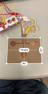
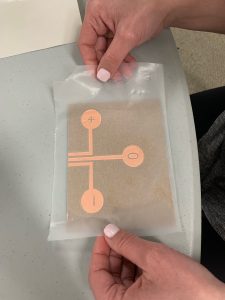
Set Up Physical Remote

  1. Cut or acquire a pre-cut piece of thin cardboard measuring 3.5 inches tall and 4.5 inches wide.
  2. Take your copper tape piece from earlier and peel off the excess copper around the box, BUT do so carefully, because you will use this excess piece on your remote.
  3. Apply this excess copper tape to the back of your cardboard piece. This should cover the bottom half of the back and have thin covering on the left and right sides of the back going to the top.
  4. Carefully peel off the excess copper tape from within the box.
  5. Cut a piece of transfer paper to fit your remaining image.
  6. Apply the sticky side of the transfer paper on top of the copper image. Rub it on well, leaving no air bubbles.
  7. Peel back the transfer paper. This process should take the copper with it.
  8. Apply the transfer paper with your image to the front side of your cardboard so that the three parallel lines are centered at the very top edge of the cardboard.
  9. Rub it on the cardboard well so that the copper pieces stick onto it.
  10. With a partner, carefully peel off the transfer paper so that only the copper pieces remain. Do this slowly as the copper pieces may want to peel away with the transfer paper.


Connect the Makey Makey

  1. To connect your remote to the Makey Makey, you need to acquire a Makey Makey kit and remove all its pieces.
  2. Clip one end of your red alligator clip to the left arrow on the Makey Makey and clip the other end to the left most copper line at the top of the cardboard.
  3. Clip one end of your yellow alligator clip to the right arrow on the Makey Makey and clip the other end to the right most copper line at the top of the cardboard.
  4. Clip one end of your green alligator clip to the “Space” on the Makey Makey and clip the other end to the middle copper line at the top of the cardboard.
  5. Clip one end of your white alligator clip to the “Earth” on the Makey Makey and clip the other end to the side or bottom perimeter of the cardboard.
  6. Plug the red USB connector into your computer and connect with your Makey Makey.
  7. Your remote should now be functional.


Standards

  • (7.NS.A1): Apply and extend previous understandings of addition and subtraction to add and subtract rational numbers; represent addition and subtraction on a horizontal or vertical number line diagram.
  • (Fab-Safety.1): I can safely conduct myself in a Fab Lab and observe operations under instructor guidance.
  • (Fab-Programming.1): I understand the basic structure of a simple program and can modify values, variables, or other parameters to alter its output, function, or behavior.
  • (Fab-Electronics.1): I can follow instructions to build a simple electrical circuit using conductive material, basic components, and power.
  • (Fab-Fabrication.1): I can follow instructor guided steps that link a software to a machine to produce a simple physical artifact.
  • (Fab-Design.1): I can be responsible for various activities throughout a design process within a group under instructor guidance.
  • (Fab-Safety.2): I can operate equipment in a Fab Lab following safety protocols.
  • (Fab-Programming.2): I can create a program with more than one instruction.
  • (Fab-Electronics.2): I can follow a schematic diagram and create a circuit including a microcontroller with electronic components.
  • (Fab-Fabrication.2): I can develop workflows across four or more of the following: modeling softwares, programming environments, fabrication machines, electronic components, material choices, or assembly operations.
  • (Fab-Programming.3): I can create a program with multiple instructions and branching elements as well as reading / controlling inputs and outputs on a microcontroller board.
  • (Fab-Electronics.3): I can create my own schematic diagrams and use them to build electronic circuits including microcontrollers.

Lesson Feedback