- Loading…

Students are challenged to both program an Arduino and engineer a circuit to measure a player’s temperature. In pairs, students will practice both computer and electrical engineering. Groups will simulate their circuits using TinkerCAD before manually connecting electronics and uploading their code. The device should accurately read temperature and attach to its wearer. This real world challenge also introduces students to a career in wearable technology.
This lesson is structured in a modified 5E lesson plan. Instructions for using the 5E model in this lesson are detailed on the last page of this document. The first three E’s (Engage, Explore, Explain) will focus on step-by-step instruction for using the Arduino and TinkerCAD code. The last two E’s (Elaborate & Evaluate) allow students to individualize their learning experience.
Instructors will introduce the class to Arduino and TinkerCAD. Students will first learn to power an LED after which they will program the LED to blink.
This project uses an Arduino to configure and code a prototype wearable device. To create a wearable temperature sensor, we first need to learn the basics of Arduino.
“Arduino is an open-source electronics platform based on easy-to-use hardware and software. It’s intended for anyone making interactive projects.” It is comprised primarily of two parts: a physical microcontroller (board) and computer-based IDE (integrated development environment).
Source: https://www.arduino.cc/
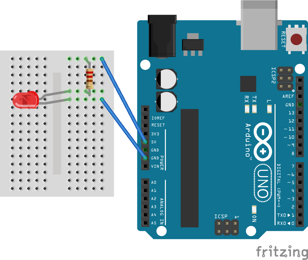
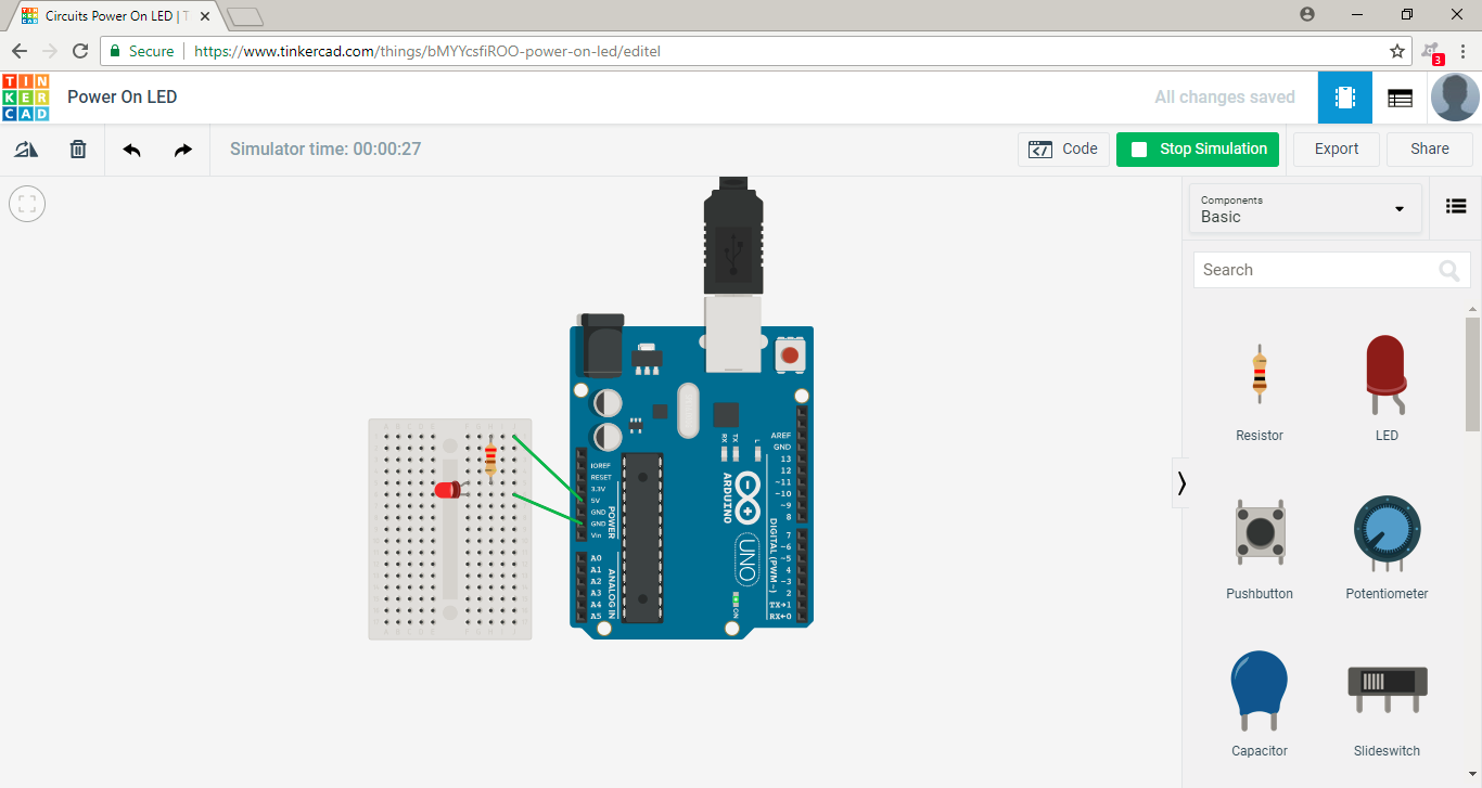
Divide students into pairs. Inform them that one student will serve as the “Electrical Engineer” the other will be the “Computer Engineer”. Throughout the lesson, these roles may interchange. Their first task as a team is to turn on an LED using a set of materials. They are also tasked with confirming their electrical configuration will power the LED using TinkerCAD Circuits.
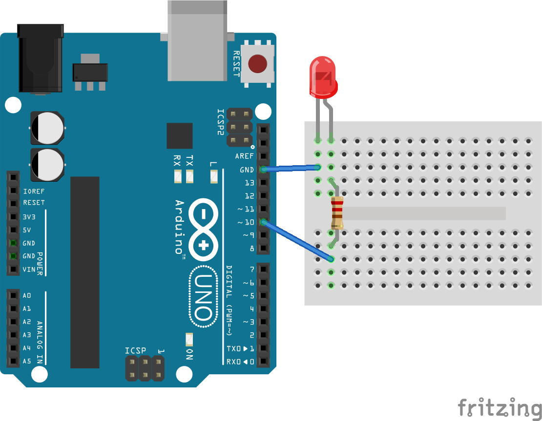
Challenge: Use the Arduino to power an LED
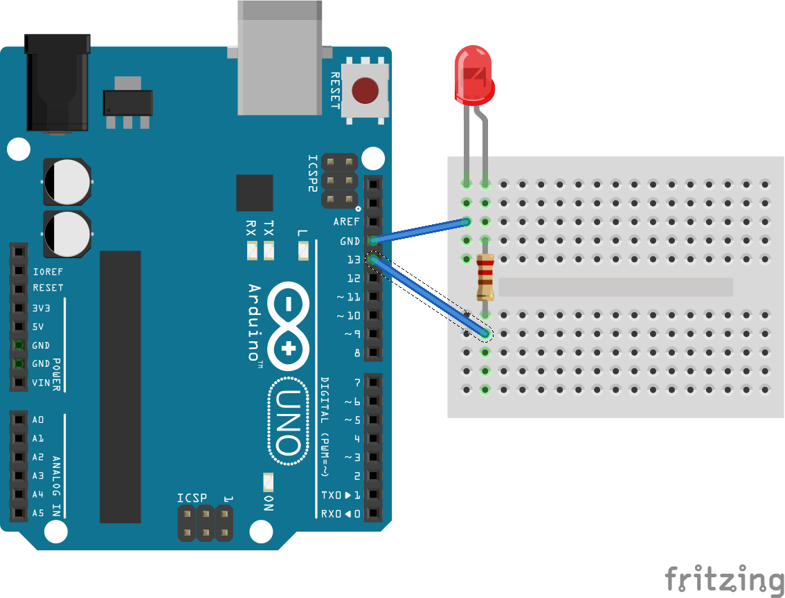
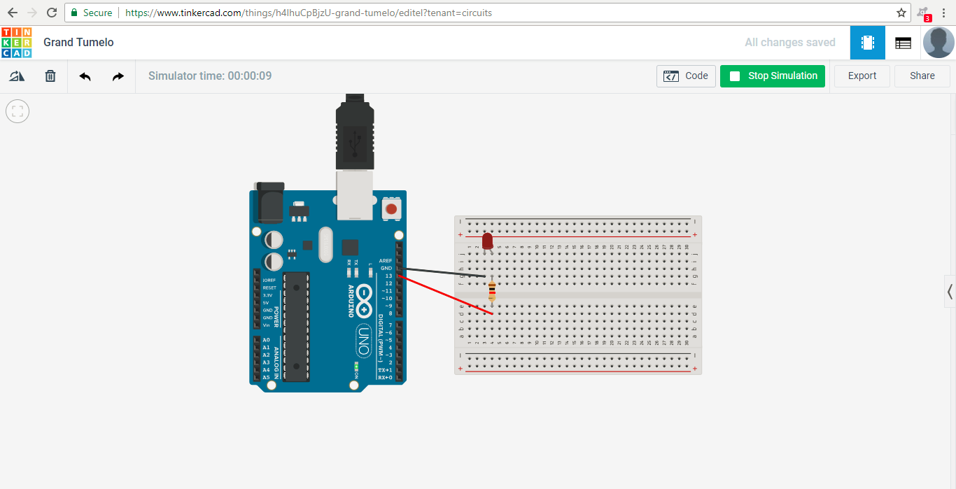
Student’s next task as a team is to program an LED to blink. They should continue to configure the physical circuit with the Arduino and confirm the configuration with TinkerCAD Circuits.
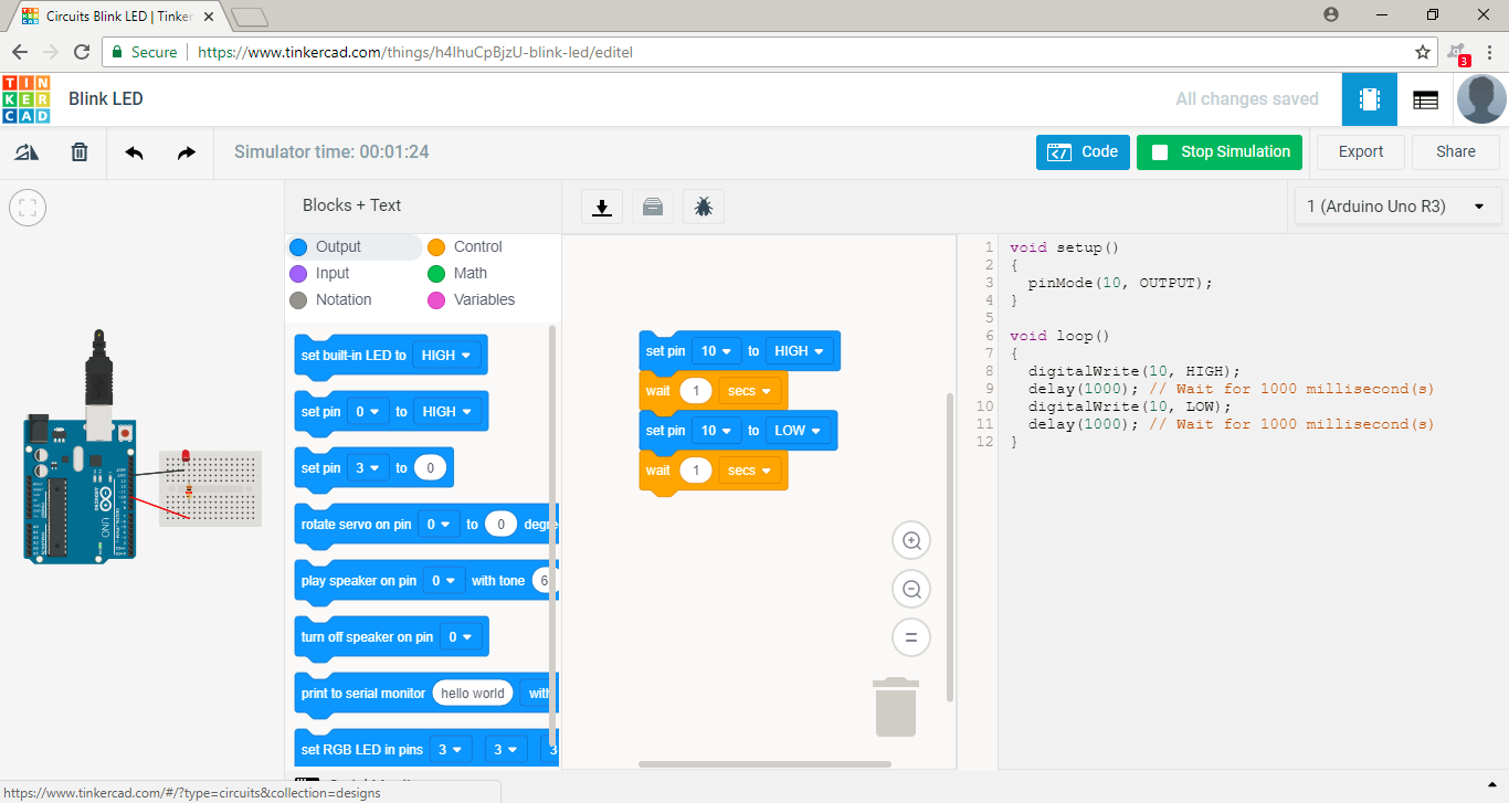
Challenge: Program an LED to blink using the Arduino
Breakdown the Arduino Components & Code:
Explain how a (mini) breadboard functions: Rows of pins (holes) are connected by conductive metal strips and allow current to flow freely while remaining separate from adjacent pin columns.
Explain the LED and polarity: Polarity means current can only flow in one direction. The longer lead of the LED is the anode (+) and the shorter end is the cathode (-). Current flows from a source of higher potential energy to a source of lower potential energy. Connect “+” sources to the anode of the LED and “-” sources to the cathode of the LED.
Explain the Arduino code:
setup() function runs once and establishes features or “rules” of your code
pinMode(“pin, “mode”) establishes a pin and mode: modes can be OUTPUT or INPUT
loop() function runs indefinitely unless prompted to stop
digitalWrite(“pin”, “value”) sets pins to a value: HIGH for on, LOW for off
delay(“ms”) wait for a set amount of milliseconds
Comments (noted as “//”) notate the code within the file. Comments are not read by the computer but are instead helpful reminders about the code. In TinkerCAD, it’s “Notation”.
Instructors will guide the students through their first attempts in writing code through TinkerCAD's block code editor. Instructors will teach students how to read digital information using sensors and discuss the differences between sensors and actuators. Students will explore writing code to program the Arduino. They will change variables and select lines of code to understand the commands they program.
Revisit the previous Blink challenge and ask students the following questions:
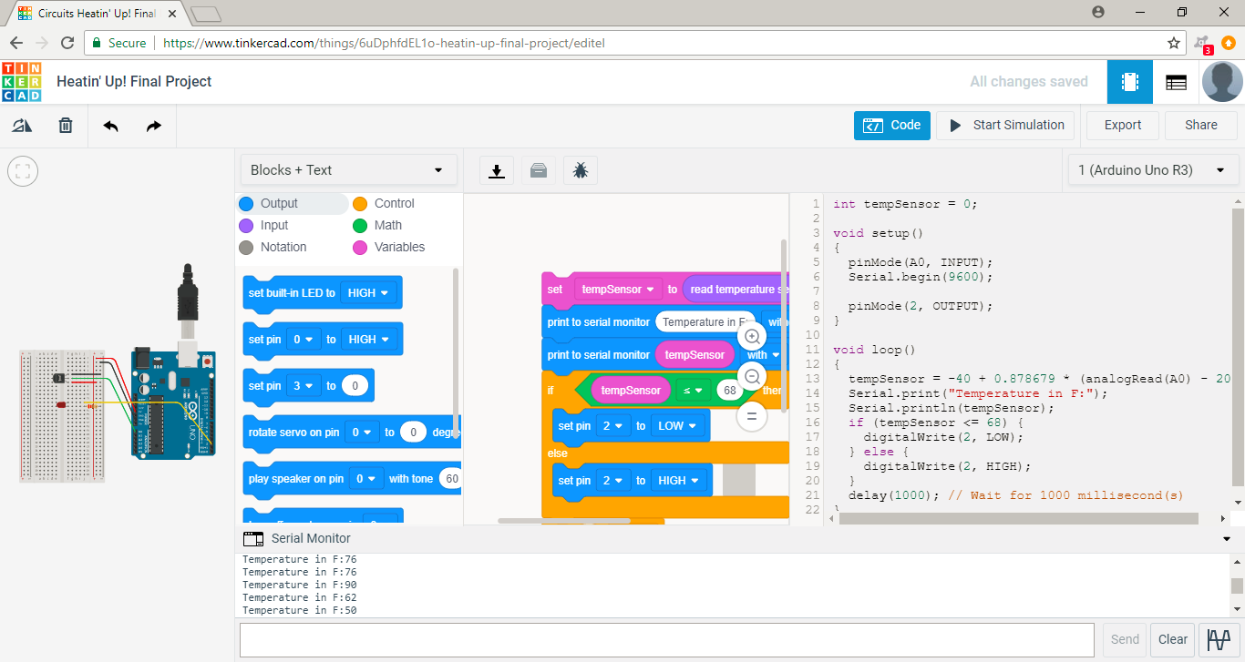
Open TinkerCAD Circuits and select the Code button to bring up the display pictured above. Use the dropdown menu to select Blocks + Text. Students can view the blocks and how it writes the real Arduino code by adding to the work plane. Both engineers will practice coding together.

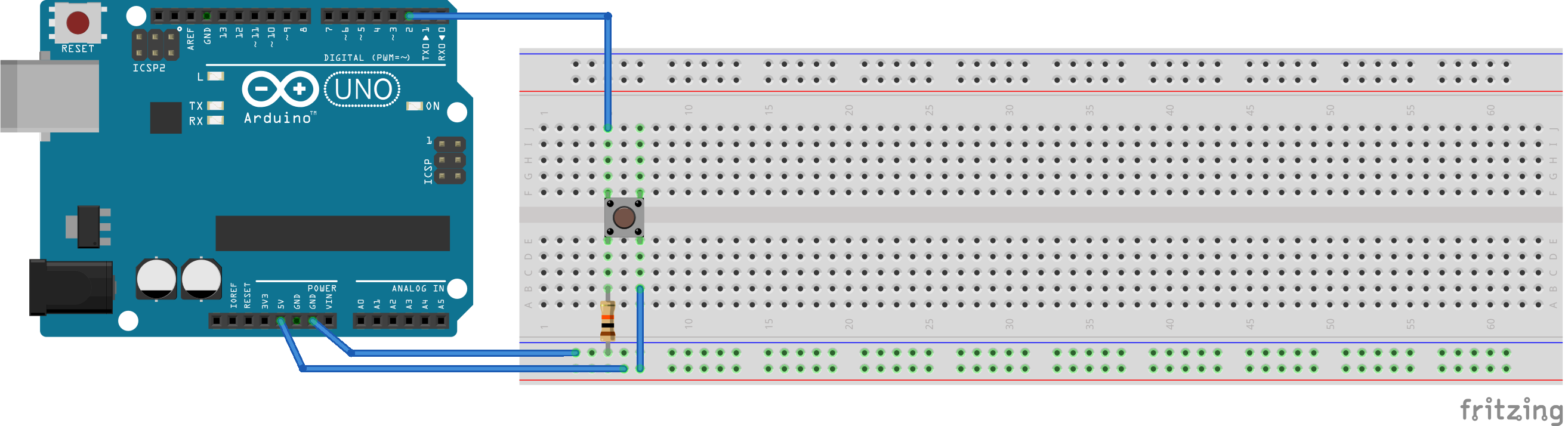
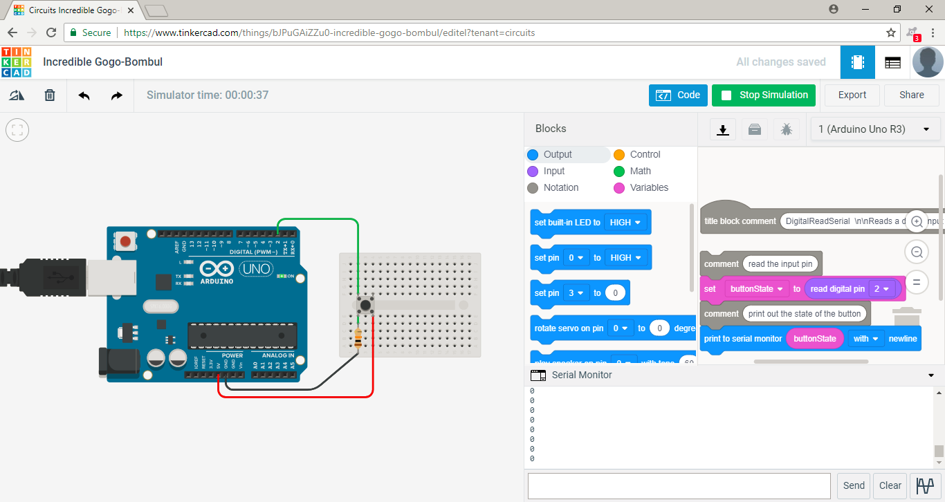
Challenge: Read digital information from the Arduino by pressing a pushbutton switch.

The Arduino board is a microcontroller. These devices take in and send out information. More specifically, “microcontrollers listen to sensors and talk to actuators”. Students have now explored both an actuator (LED) and sensor (pushbutton switch). Additional examples of each are as follows:
Sensors: Temperature sensors, Accelerometer, Motion sensors
Actuators: Sound buzzer, Motor (servo motor), Piston
“Things that convert other forms of energy into electrical energy are often called sensors, and things that convert electrical energy into other forms of energy are sometimes called actuators.” (Source: Arduino)
Instructors will discuss the differences between digital and analog information. Instructors will continue to break down specifics of code for students. Students will continue to explore writing code. They will use both sensors and actuators to combine their knowledge from the previous lesson and today.
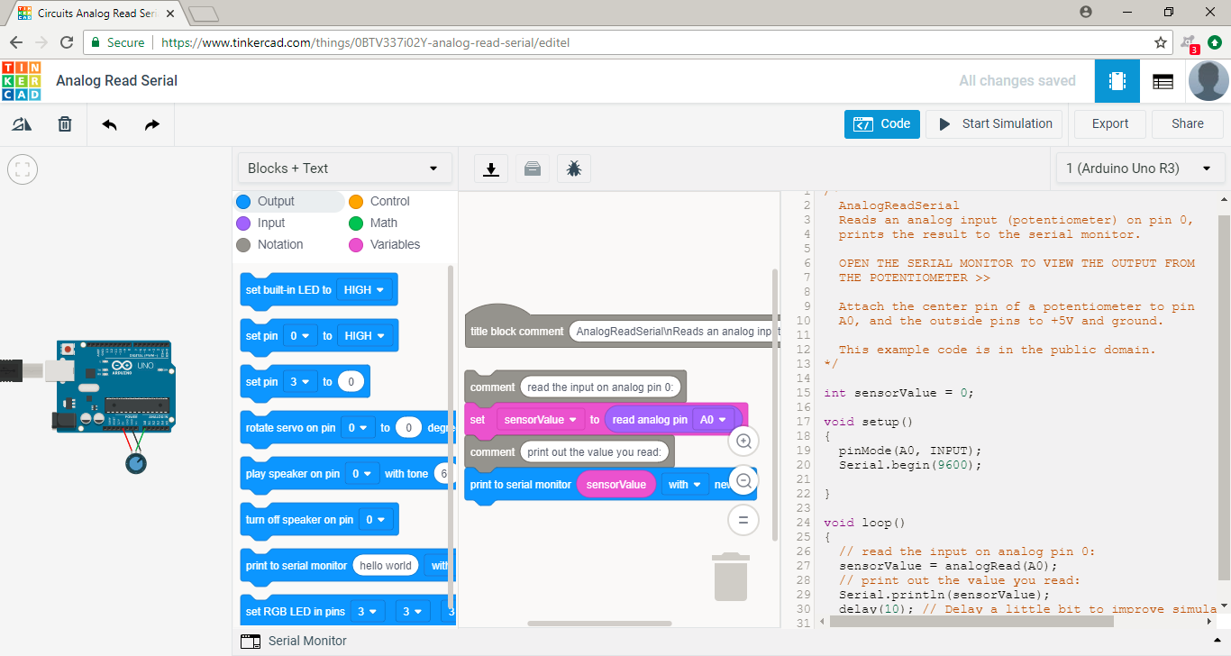
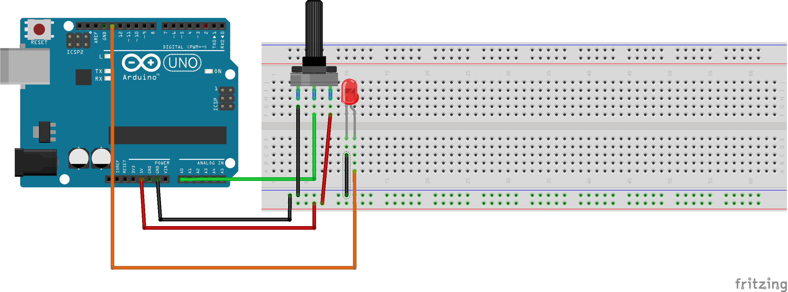
Challenge: Read analog information from the Arduino by using a potentiometer.

Arduino Code Breakdown II:
Serial.begin(9600) – talk between computer and Arduino at the standard 9600 bits/second
digitalRead(“pin”) – inspects a digital pin
analogRead(“pin”) – inspects an analog pin
Serial.println() – prints data defined within the () on a new line in the Serial Monitor
Analog: information existing on infinite range, ex. numbers from 0 to infinity.
Digital: information existing on a limited range usually in two states, Ex. 0 to 1.
Arduino has a built-in Analog to Digital converter. In the previous challenge, it converted analog voltage information (0-5V with an infinite range of values in between) to a number 0-1023.
Potentiometers are essentially resistors. Twisting the knob varies the resistance by “changing the ratio of the voltage between the middle pin and power.” They are similar to light dimmers.
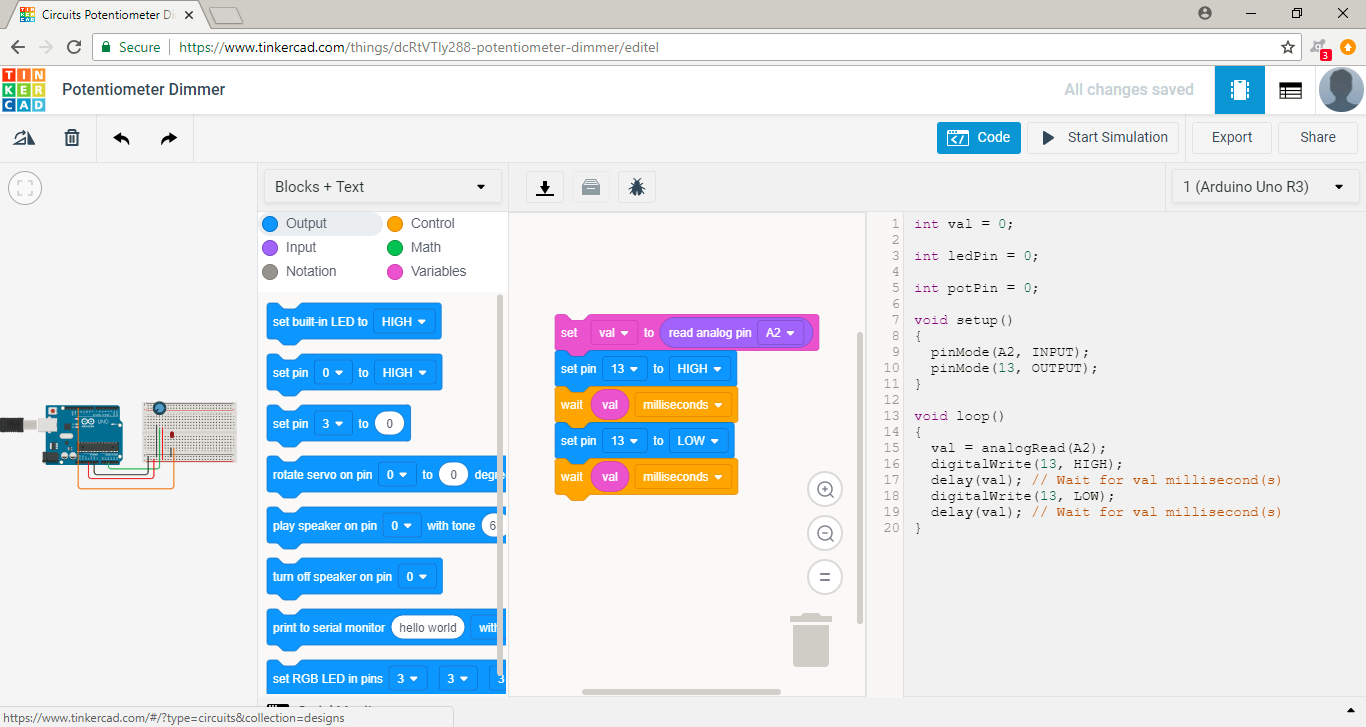
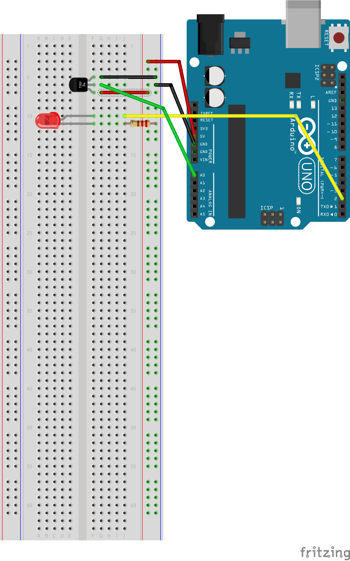
Challenge: Program an LED to blink using input from a potentiometer

Instructors will show students an an application of the final product (if they have not already done so). Instructor will guide students through the more challenging lines of code and electrical setup. Students will apply their knowledge of Arduino electronics and programming to create a Temperature Sensor that accurately tracks the surrounding environment.
Introduce students to the final challenge by showing them the following video describing build and use of a temperature sensor for safely shoveling snow in cold weather:
https://www.youtube.com/watch?v=N9gW5cmOb78
Challenge: Construct a prototype wearable device that can track a player’s temperature data.

Instructors will use additional digital fabrication tools to allow students allow students to go beyond the original temperature sensor electronic setup and programming. Students will think creatively of how to use their temperature sensor or ideally wear it by creating additional features through the use of digital fabrication tools.
Students can begin to redesign their temperature sensor by making it more of a wearable device. The following technologies could help improve these Arduino coded devices:
Modifying the Code
Changing lines of the code to read in new information and write or present different data could improve the overall experience with the device. One example might be to add several LEDs and create a light meter wherein more LEDs light up the greater the temperature.
Additional Electronics
The addition of extension wires, solder connections, header pin connecting cables, battery adaptors, and any other devices could increase the device’s portability, accessibility, and comfort.
Vinyl Cutting
Custom designed patches could apply the sensor of the device to the wearer’s skin or clothing. These could allow for the sensor to securely and accurately measure temperature while the wearer performs various activities. Additionally, it could also add to the aesthetics of the device.
3D Printing
Crafting a housing unit using CAD software (like TinkerCAD) to compactly store the Arduino while using the device protects both the wearer and the Arduino.
Instructors should refer to this section of the document for each Arduino activity. The prompts will guide instructors in employing the 5E lesson model throughout the lesson.

Having trouble? Let us know by completing the form below. We'll do our best to get your issues resolved quickly.
"*" indicates required fields


Thank you for your fab contribution!