- Loading…
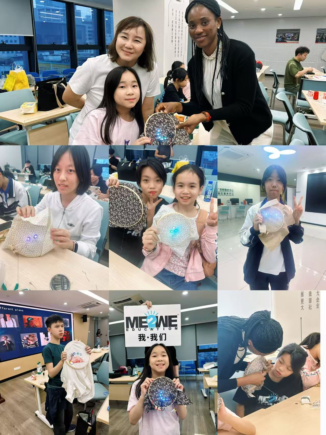
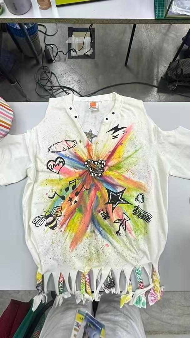
Through this course, students will learn the complete process of circuit board design and fabrication, and realize simple wearable functions by sewing the circuit boards onto clothing.
– Cross-stitch auxiliary tools
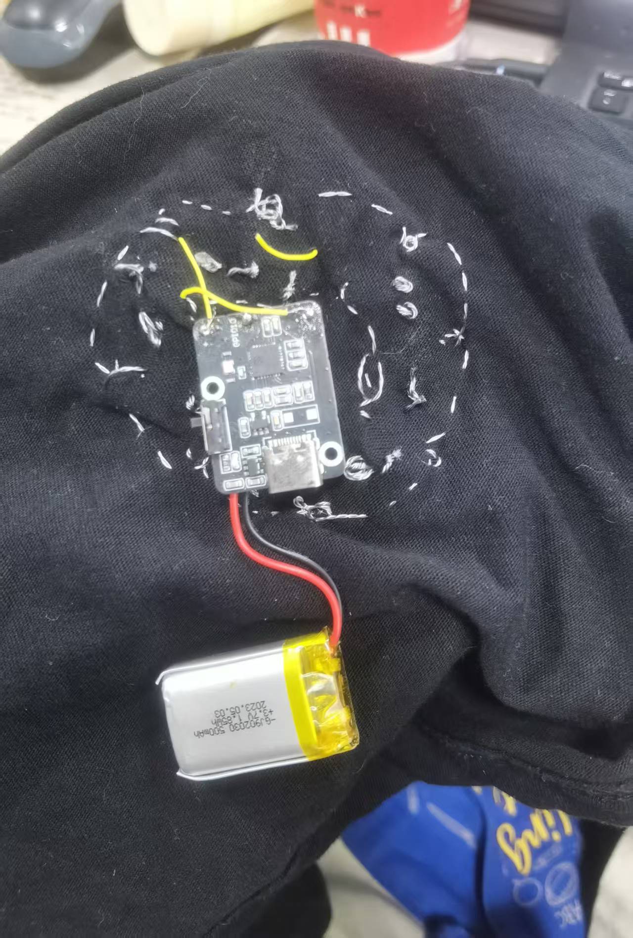
– Mainboard
– Battery
– Needles and threads
– Fabric
– Control panel
– Conductor wire
– Nail polish
– Scissors
– Sensors(3-8 pieces)
– Pencials
The general idea of this course is to help students master the basic knowledge of Batter-Resistor Circuit
The general idea of this course is to help students master the basic knowledge of Batter-Resistor Circuit. So at the beginning of the course I need to show the work flow of the batter-Resistor Circuit. Students will understand better then we move to our main board introduction and how sensors work. Short circuits are likely to occur during the sewing process, so some tools are needed to assist students in completing the project. Since the process is also relatively time-consuming, students can start by implementing the wearable function with 3 sensors. Those who have extra capacity can increase the number of sensors to finish their works within the limited class time.Make sure the course is both flexible and challenging.
Through this course, students will learn the complete process of circuit board design and fabrication, and realize simple wearable functions by sewing the circuit boards onto clothing. At the same time, students will understand the basics of simple circuit design, how to achieve electrical conduction, and the fundamental knowledge of how positive and negative poles work with resistors to enable current flow.
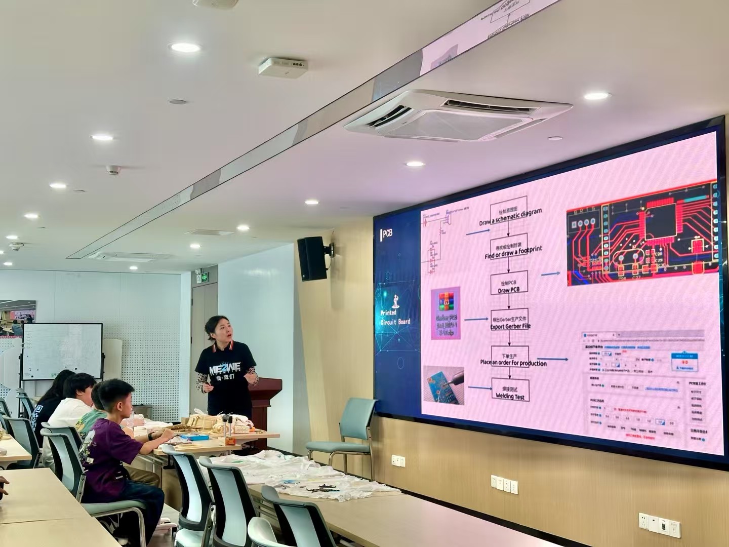
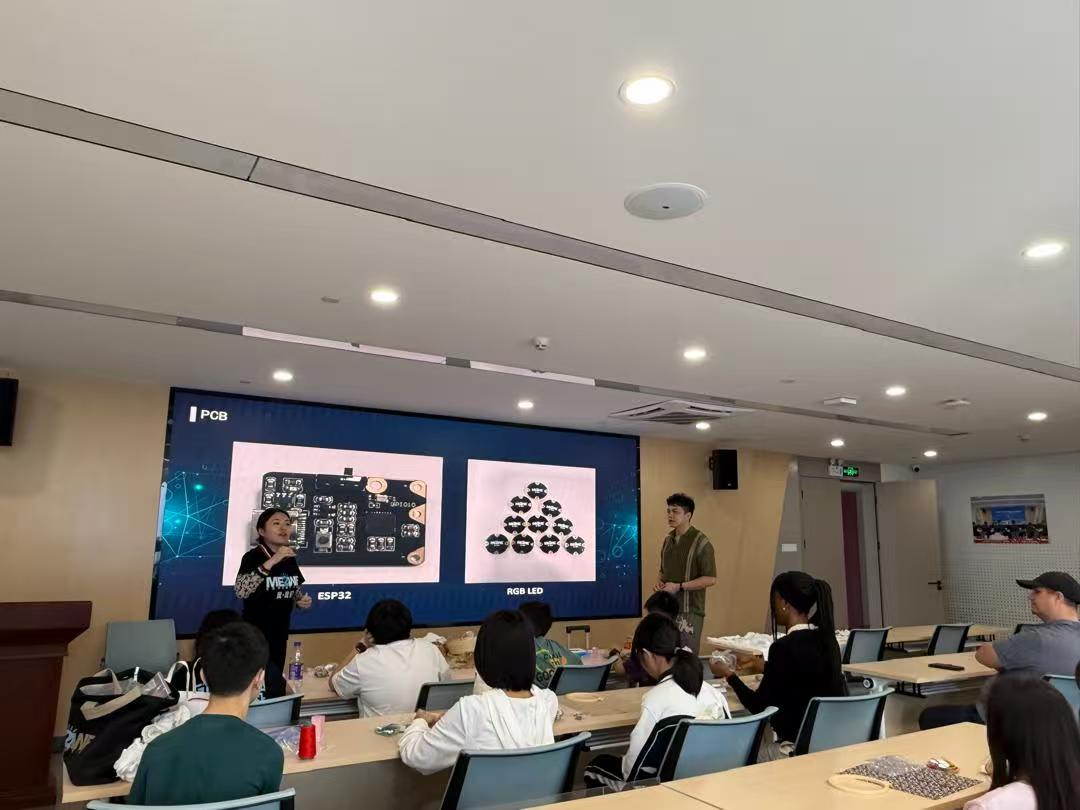
Show our PCB
https://phet.colorado.edu/sims/cheerpj/battery-resistor-circuit/latest/battery-resistor-circuit.html?simulation=battery-resistor-circuit
follow the links to understand the fundamental knowledge of how positive and negative poles work with resistors to enable current flow.
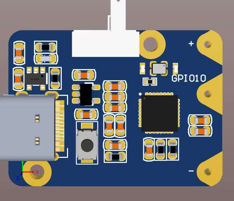
There are 6 steps to make PCB . 1.Draw a schematic diagram 2.Find or draw a footprint 3.Draw PCB 4.Export Gerber File 5.Place an order for production 6. Welding Test

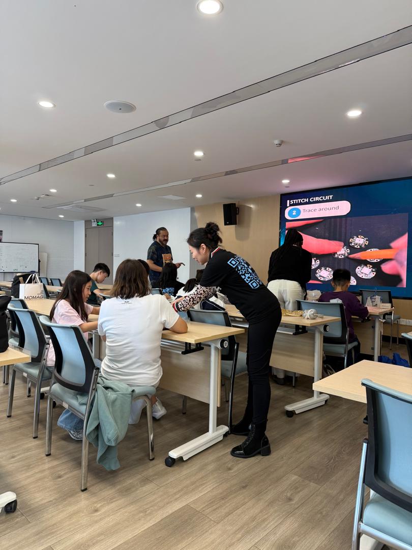
Let's start stitching. 1. Place a hoop 2. Trace around 3.Start stitching 4. Trace the perimeter 5. Plug in the USB cable

Test your new components' connections to GEMMA with a multimeter. If everything checks out, plug in your battery and pat yourself on the back!

NeoPixels are chained together with data input coming from GEMMA GPI0, all + to Vout and all - to +.All positive connect with positive , and the same time negative connect with negative.

Having trouble? Let us know by completing the form below. We'll do our best to get your issues resolved quickly.
"*" indicates required fields