- Loading…
This project will lead a group of aspiring drivers through iterative discussion, ideation, and design along the steps to build a rolling chassis out of popsicle sticks, assemble it with a breadboard, Arduino uno, A motor and a servo, then drive it through some basic pre-programmed shape routes.
In addition to standards reported, this lesson aligns with:
CSTA 2-AP-13: “Decompose problems and subproblems into parts to facilitate the design, implementation, and review of programs.“
CSTA-2-AP-15: “Seek and incorporate feedback from team members and users to refine a solution that meets user needs.”
Prepare a TinkerCAD Class for students ahead of time, it saves trouble with logins.
Each phase should be prepped ahead of session, with scaffolded models which help each student start from the same spot. This helps ensure that the 3 major sections can happen in about an hour each.
For the build section, parts can be manufactured from popsicle sticks, and cardboard, easily cuttable with laser. 3D printing can be done with PLA, and it can be up to instructor how much of each to do. It may be necessary to schedule manufacturing outside of class time, but an optional step is included for doing a laser cut with students.
Circuitry components:
Optional additions:
Students will discuss as a group to consider fundamental constraints for their project, weighing visual components with functional ones.
Students will apply geometric measurement to define shapes in TinkerCAD to match real world components.
Students will arrange geometric shapes in TinkerCAD to create 5 parts which might be laser-cut from popsicle sticks.
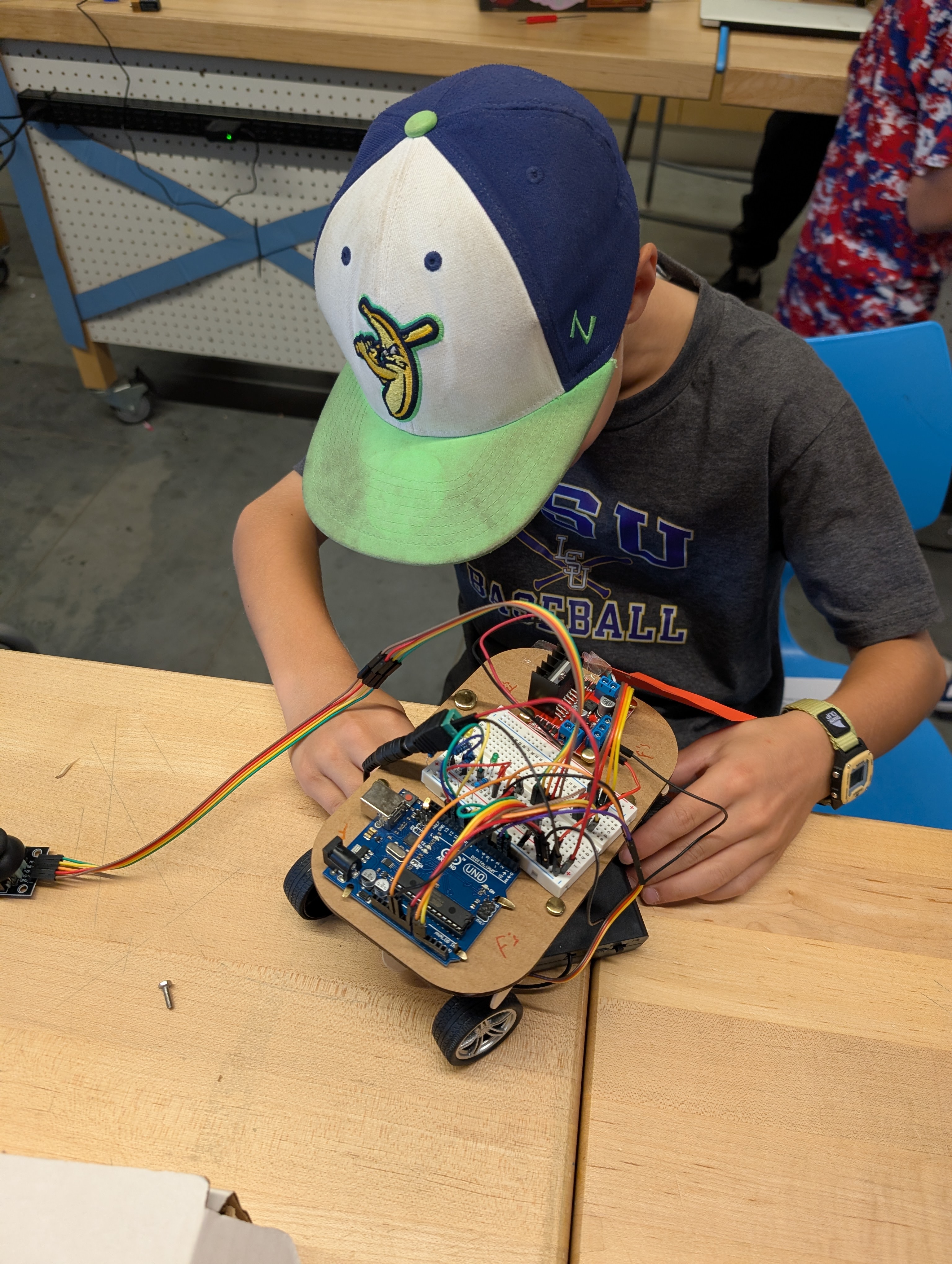
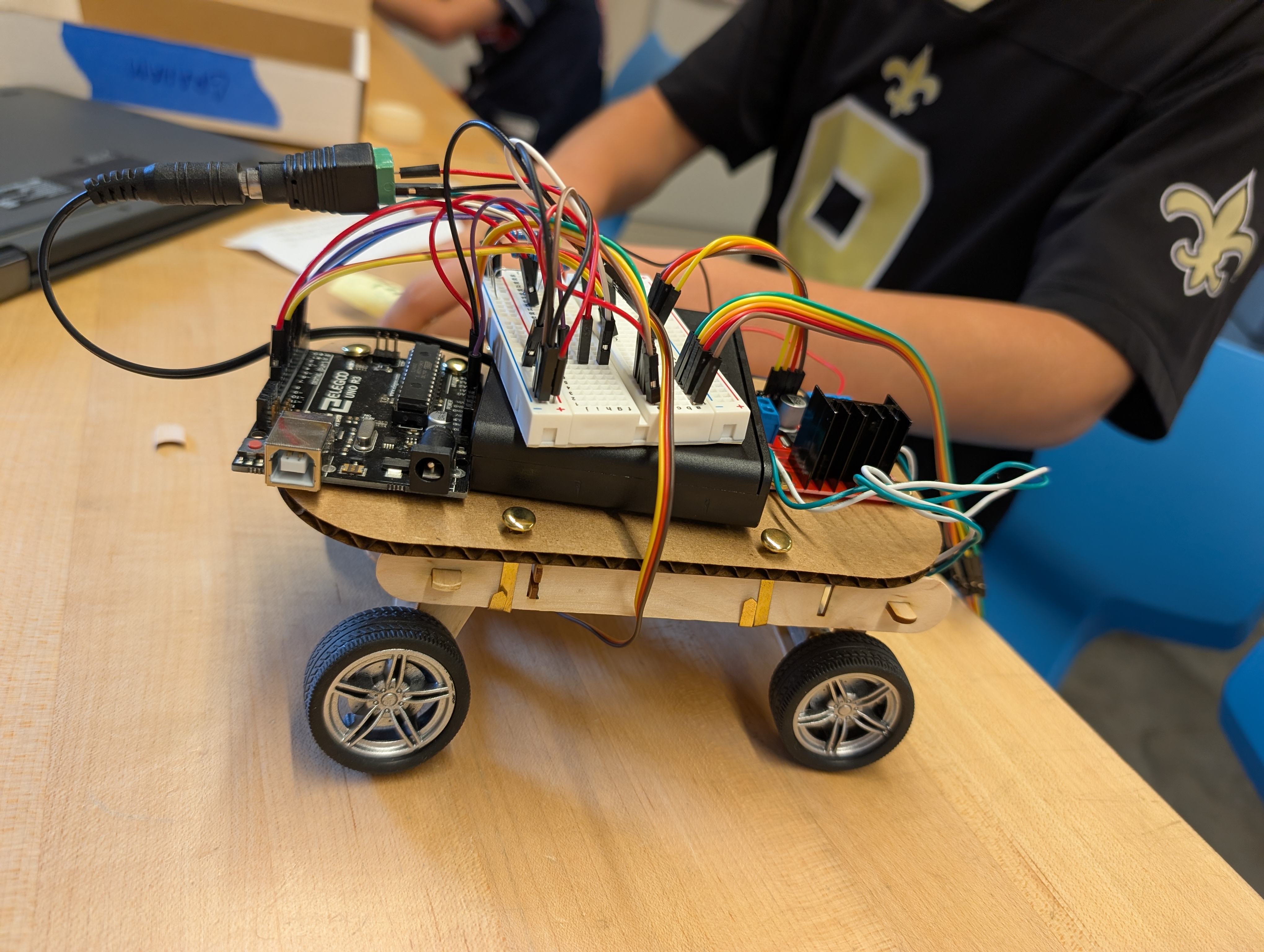
Students will assemble the car with provided wheels, motors, a cardboard body and electrical parts.
Students will program the circuit to manipulate their car along intentional paths.
Students will test their program with the car, and adjust for deviations from intention.
Students will evaluate the results of the test, and collaborate to compare results and troubleshoot issues, communicating reasoning to peers.
Students will confer with peers to describe the relationship between motor direction signals and physical car motion using cause and effect reasoning.
Students will propose an iterative change to their assembly in order to address the structural needs they discover.
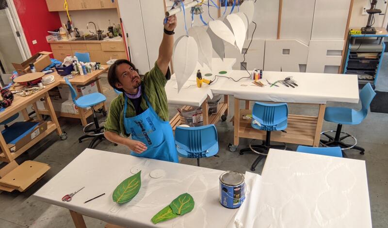
During the Lesson delivery, learners struggled with handling tools, admittedly because some of those tools were poorly matched to the scale of the parts in question (not all precision screwdrivers are as precise as needed for a 1.6 mm screw.) I had anticipated more problems during design, but those seemed less than they have for previous iterations of Dig-Fab lessons. Nevertheless, the activity is built around “Checkpoints” where on a periodic basis, a student who has fallen behind in a task or two can be directed to just open the next file, where a model that snaps the student’s progress to align with everyone else in the group.
When it came time for testing Student builds, there were lots of big feelings from students about a much anticipated result that proved a further need for checking assembly.
In testing, there is an uncomfortable degree of joint relationships which need resolving. I mean to reach a point where hardware is no longer necessary, and the interlocking relationship already in use, it seems like it solid improvement to make.
Before designing with computers, Start by understanding the needs of the project on paper.
Meet as a group to discuss and sketch ideas for what a self-driving car might look like.
As you draw, ask the following questions:
At the point where you can no longer do away with any feature and still have enough of a car, test your car concept with a peer, and see if they agree. If all of your peers agree there is nothing else that could be removed, It might be time to move on to the next step.
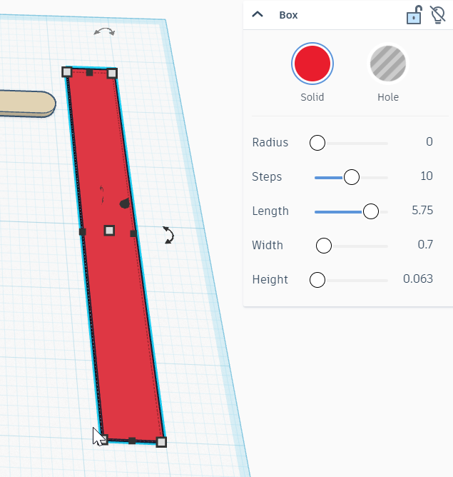
In this project, we will be creating with popsicle sticks, but in a different way than normal. To use as few parts as possible, we will create a series of modular joints to allow these parts to be assembled without even needing glue or hardware, with enough stability to hold our electronics aloft for a light and nimble ride. TinkerCAD already has a popsicle stick, which we can bring in as a shape, finding them in "Everyday Objects > Wood Stock" or just by searching in the panel for "popsicle stick" But what about our jumbo-stick? No problem, we can make our own.
Measure the physical jumbo stick to get its length, width and height
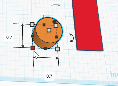
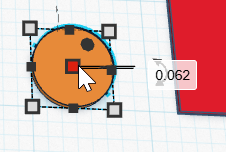
Make your own jumbo stick by combining a box and two cylinders.
Hold the “Shift” key and click the box and one of the cylinders, then press “L” to use the align tool.
Select all three shapes, then hold “Ctrl” and “G” to use the Union Group tool, joining them into a new Jumbo Popsicle stick!
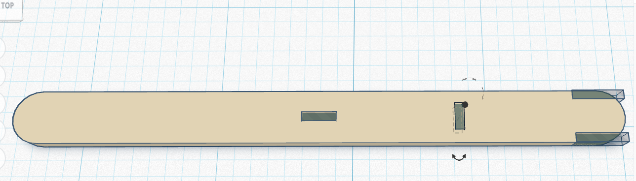
This step will add a series of specific holes to the standard sized stick, turning it into the first of our 3 modular parts.
To start, drag in the box hole and set its size so that
Use the align tool to align the hole to the forward and right of the stick.
Hold the “alt” key and click and drag the hole to create a copy. Align it with the back right of the stick.
Repeat the “alt” drag to create another copy, and align it to the center, center of the stick.
Then “alt” drag this hole once more, but don’t align it just yet.
Hold the “Shift” key and click each of the holes that was aligned, then “Ctrl” + “B” will Bundle Group the holes.
Now, Shift click to include the unaligned hole, and center it within the others.
Click and drag across the stick and all the holes except the one at its center.
Click somewhere in the stick, then click and drag it stick to move the copy we didn’t know we created in the last step, without any of the holes. It will be needed it in a later step.
Click and drag to select the first stick with all the holes, then “Ctrl” + “G” to Union Group which will create a new part out of all the selected ones, allowing the holes to really look like holes.
Hold the “Alt” key and click and drag the grouped stick to make a copy WITH its holes.
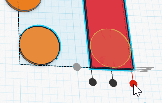
Add a box hole at either end. Don’t worry about changing its dimensions, the 25.4 mm cube will do fine here.
Align them to the ends, and so that it covers thoroughly where it overlaps.
Select the stick and both Box Hole ends, and “Ctrl”+G to group them into a shortened version of our first stick.
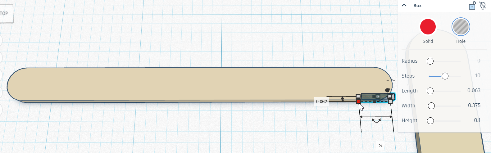
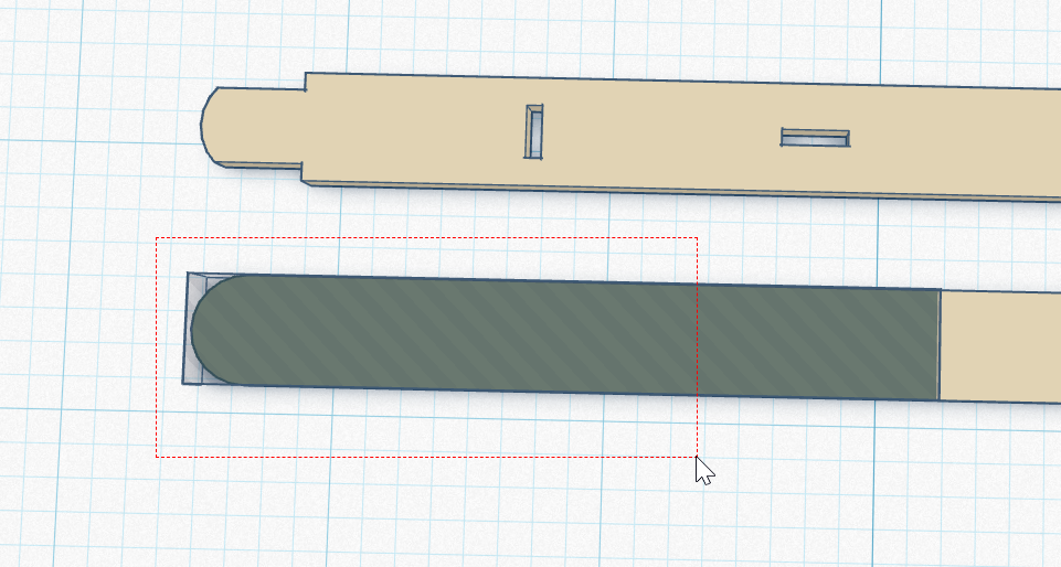
This stick needs some holes in precise places to accommodate the small motor that will drive this car.
Recreate the first box hole on the new stick, but set it with different length and width.
Next drag in a box hole that is matches the front to back and top to bottom sizes of the stick, with a side to side length of 68.6 mm.
Drag in a Cylinder hole, and size it to have width and length of 3.5 mm, and height to 3 mm
Drag it into position where it is centered in the short stick, 9.5 mm from an end.
Add two more cylinder holes, on either side of the primary.
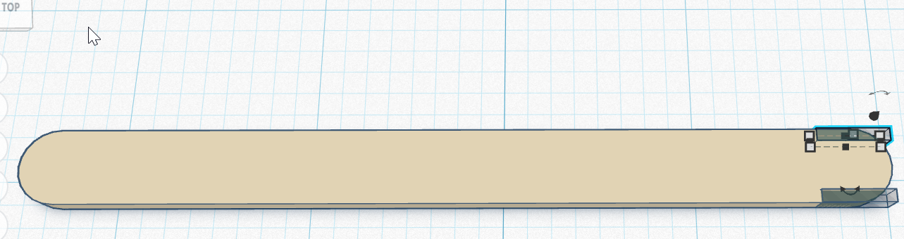
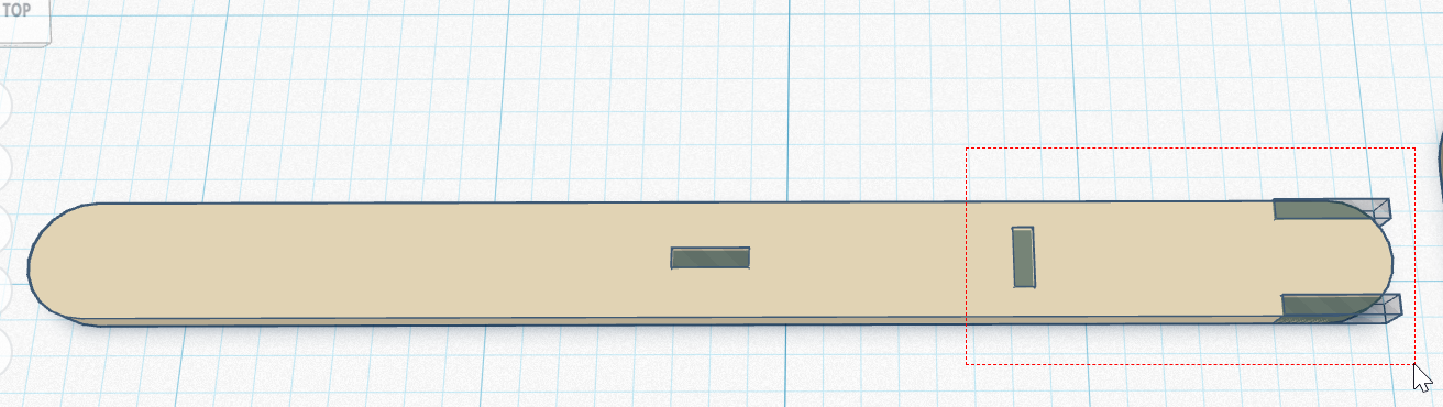
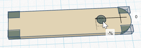
The last set of cuts will be made on the jumbo stick.
Finally, create one more box hole, and put it into the jumbo stick.
It should be centered across the width, and far enough from one end to not overlap any of the round part.
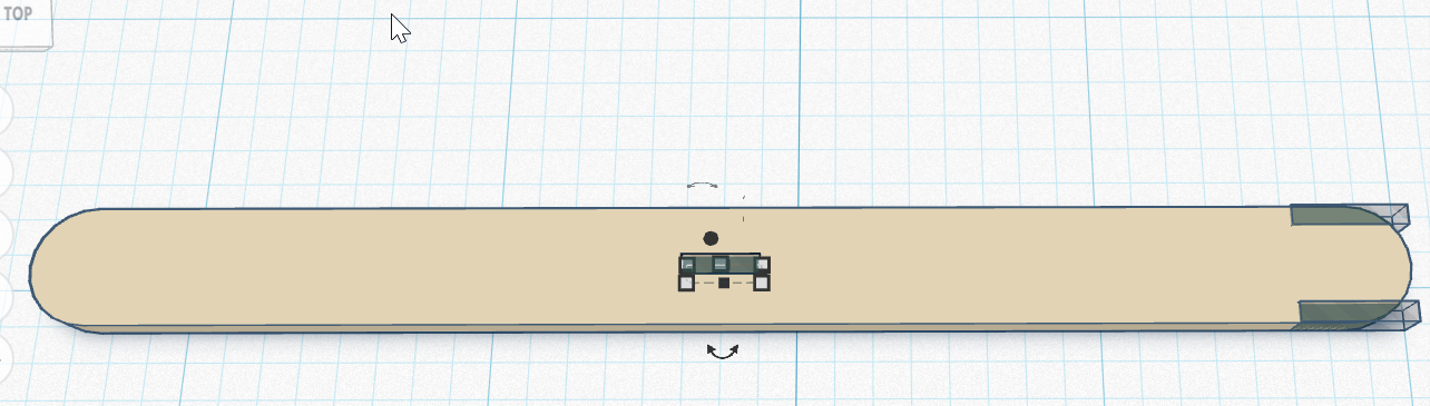
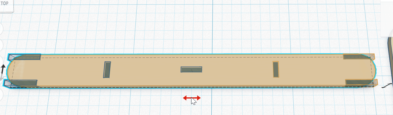
Duplicate it to the other end, then group the two holes and use the align tool to balance them within the length of the Jumbo Stick.
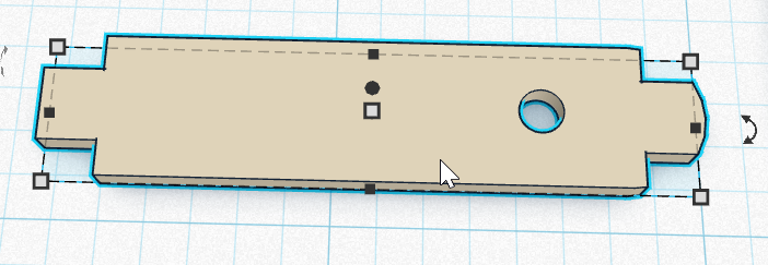
Select the jumbo stick and both of its holes, then hold the alt key while clicking and dragging to the right to duplicate-place a new copy right next to the original.
select each box-hole, and change its dimensions to be the stick-thickness from front to back, and standard stick width from side to side.
Realign them to the center of the jumbo stick, and balanced with the original holes still present on the previous jumbo stick.
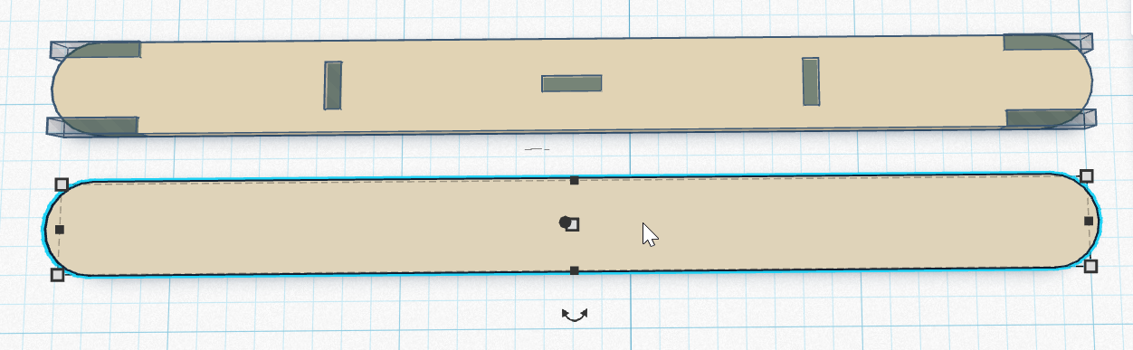
Group them into the final stick.
These parts will need to be exported to be laser-cut. This section includes a scaffolding measure: Guiding the students through setting up their own individual laser files is of course noble, but runs into a bottleneck if there is only one terminal that can facilitate that. Students go as far as downloading their SVG part files, then submit them to be reviewed for dimensional accuracy. When they step up to the laser cutter terminal, they are executing on a pre-loaded file that has already been laid out for the goal at hand.
Click the Export button at the top right of the workspace
When the menu pops up, go all the way to the bottom and click the button for “.SVG”
Assessment check!
Part files are to be reviewed for dimensional consistency before students can operate the Laser Cutter to make parts.
To accomplish this, the included SVG file sets up a template for popsicle stick cutting. Apply a layer of masking tape to the laser bed, then run the first layer as a vector cut, with high speed and VERY low power. Ideally, it should not cut through the tape. The second layer sets up enough parts to make one batch for a car, omitting unnecessary edges which are already present in the popsicle sticks. The third and forth layers allow you to do the same, but run batches of parts, if you want to run this outside of class time, and let the class focus on build and circuits, for time efficiency. In that case, skip this step with students. A separate template is for cardboard body plates. These could also be designed custom by students, but this version simply includes it for expediency.
Open the Laser Cutter and lay each of four standard popsicle sticks and 2 jumbo sticks into the template markings provided in the blue tape.
Check the Job settings to make sure they are ready for the cut.
Confirm the job by clicking print, then watch the LCD screen on the machine to make sure the new job arrives.
Check stick alignment ONE last time, then close the lid
Turn on the Dust collector and Air assist pump
Start the job by pressing the green “Go” Button
Watch the job to its completion to ensure no fires.
The machine will beep when done. Wait until the carriage stops moving before opening the lid.
Remove ALL parts, including those which will now be scrap.
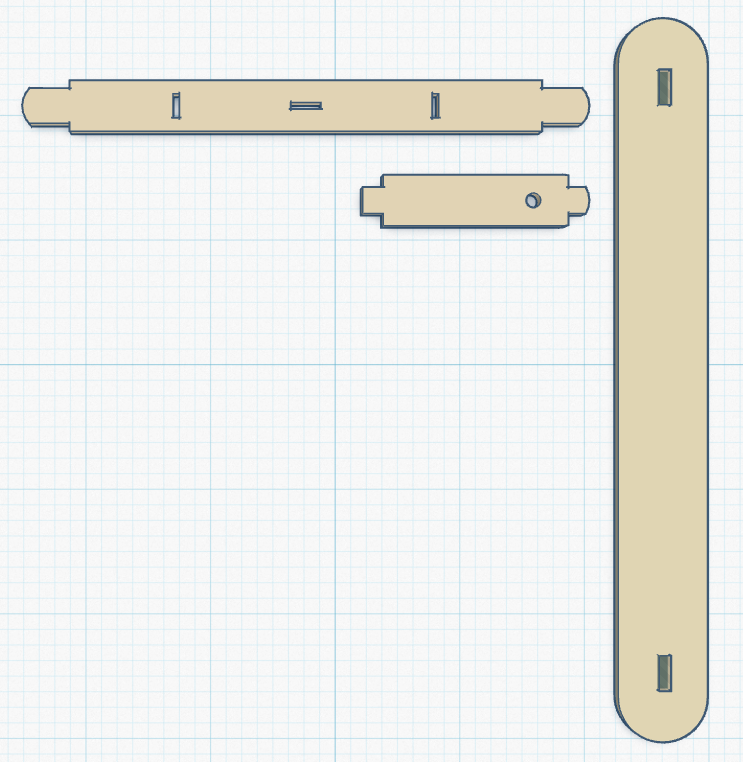
Start by orienting to the parts themselves: The shortest part with three round holes clustered near one end is the motor-riser. The next shortest piece with 3 slots is the bottom-brace. The full length standard stick with 3 slots and 4 notches is the top-brace The jumbo-stick with slots along its axis is the side-panel The jumbo-stick with slots across its width is the belly-pan The included .SVG incorporates these names, which could be used as a reference for students, or etched directly on the parts if preferred.
View a TinkerCAD Codeblocks animation that shows this process!
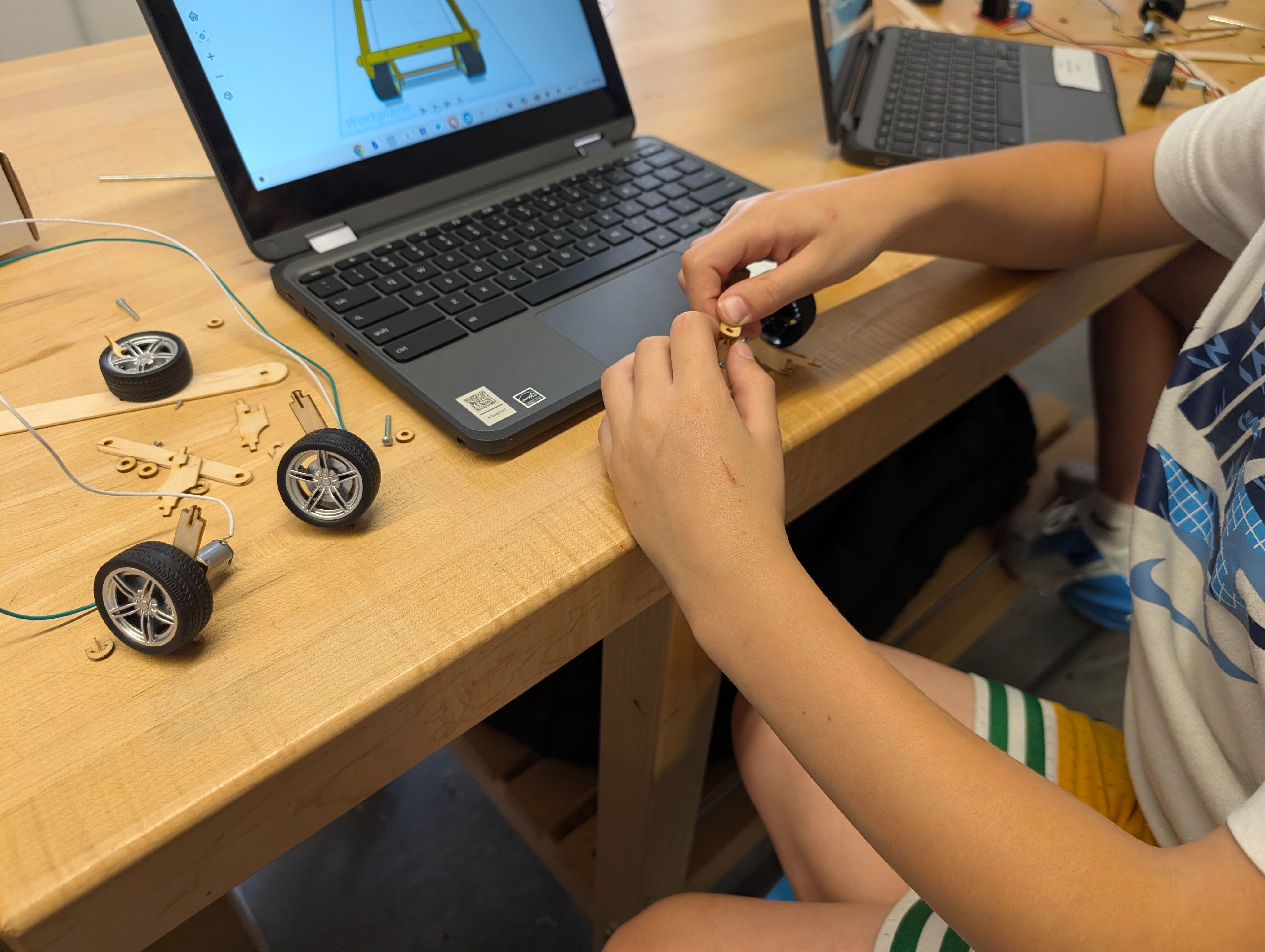
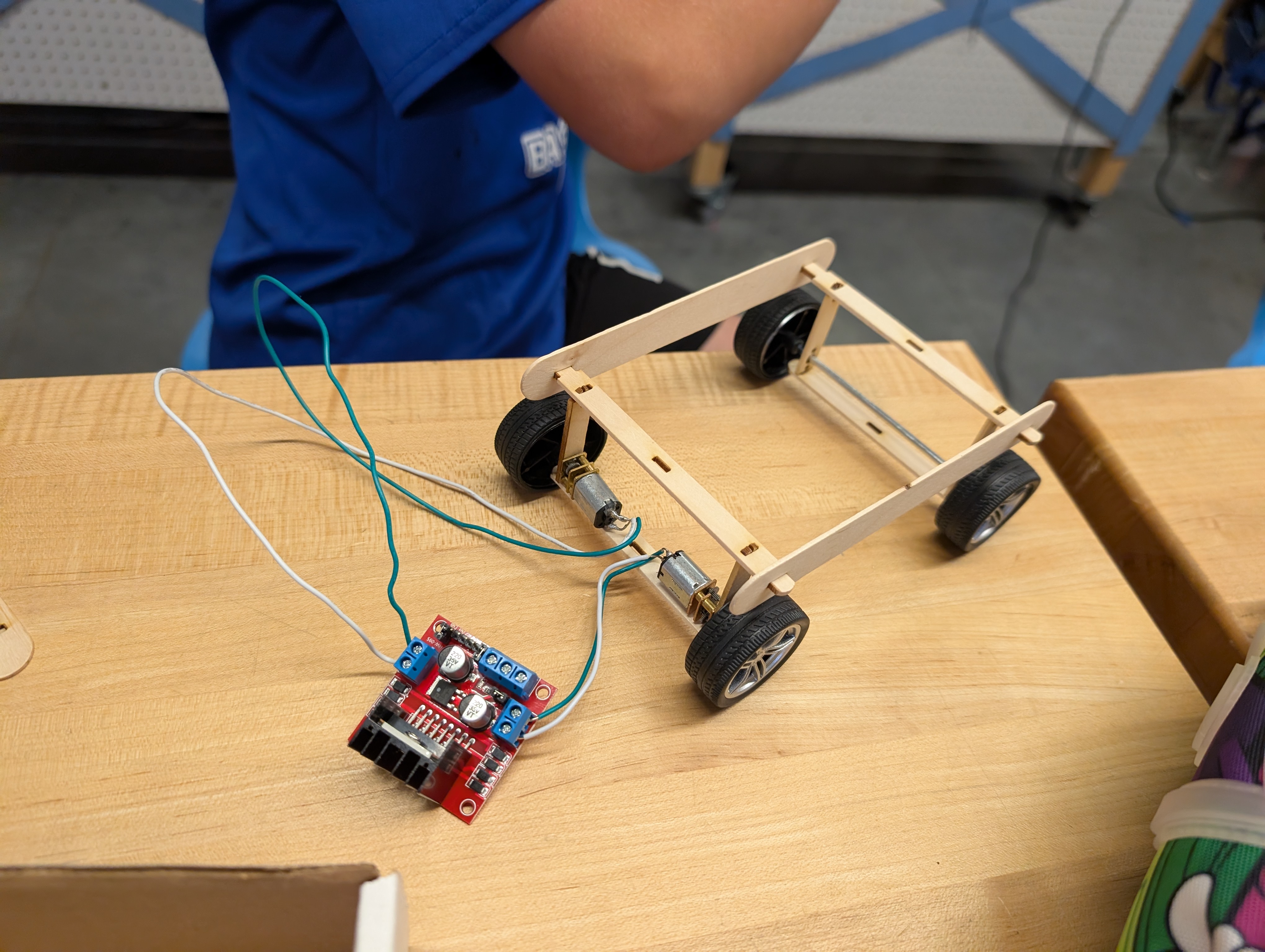
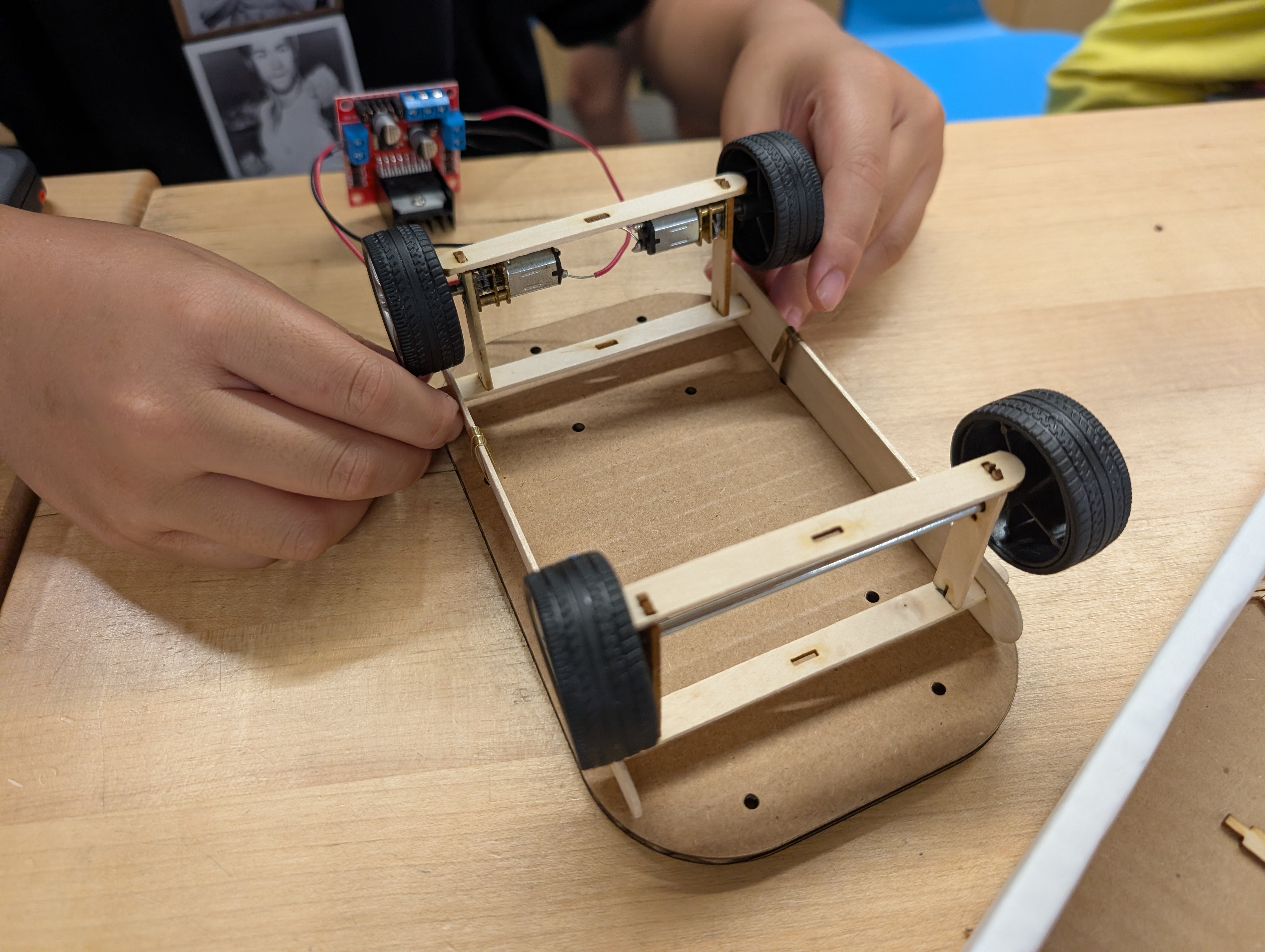
Drivetrain Sub-assembly
Front wheel Sub-assembly
Add the Side panels.
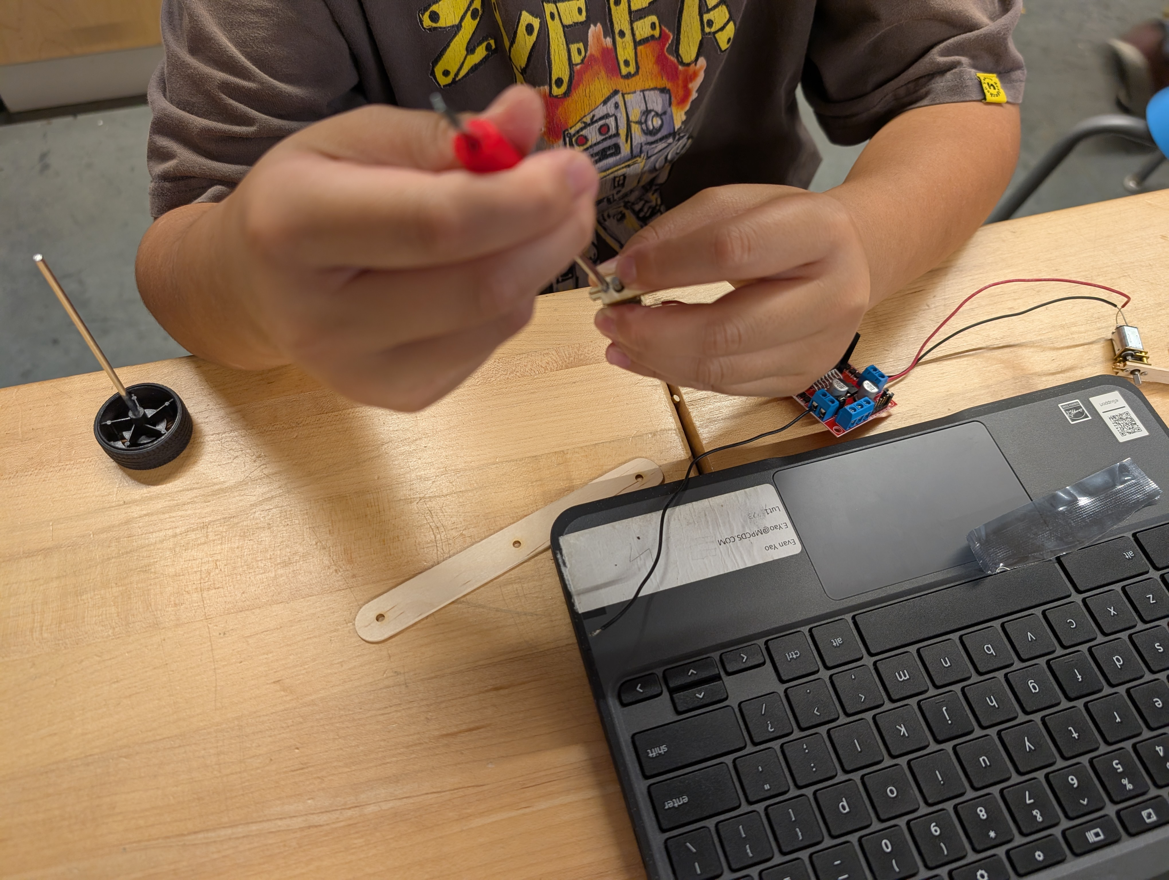
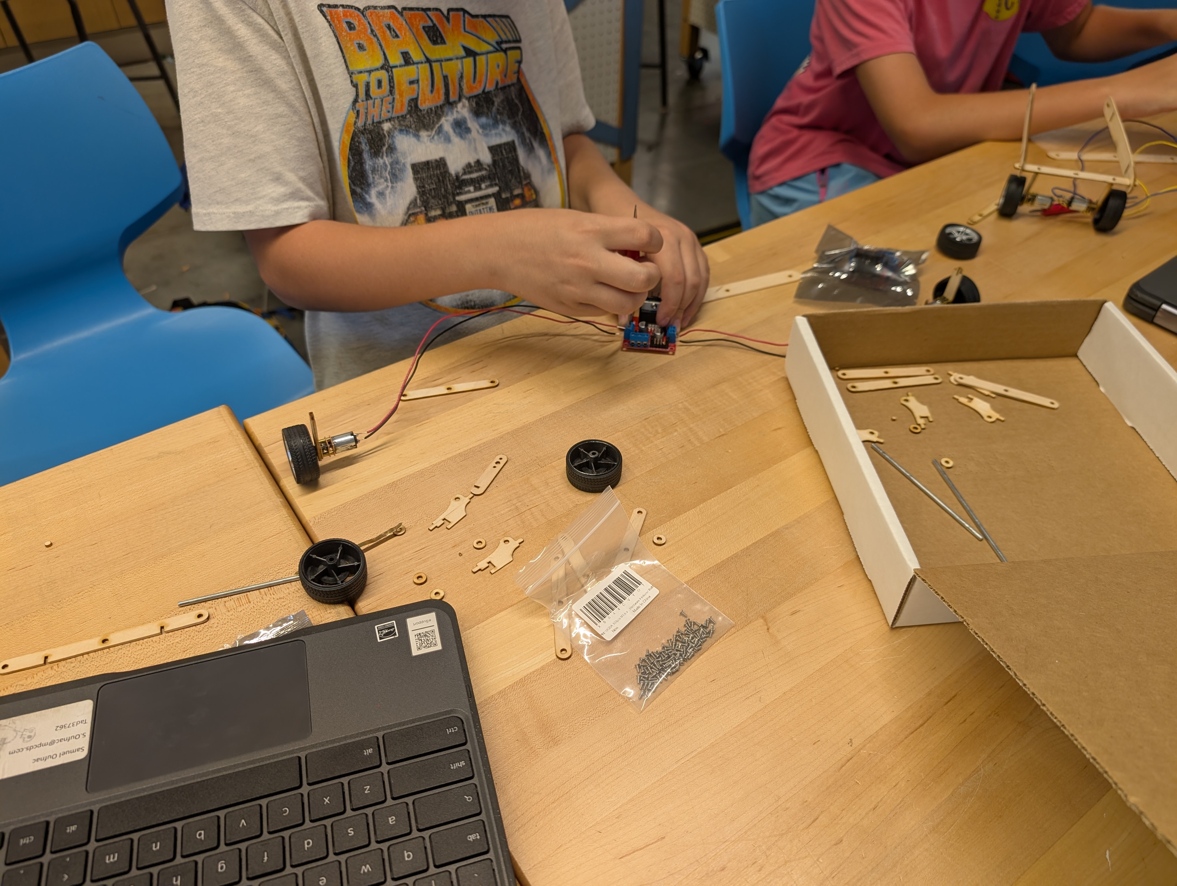
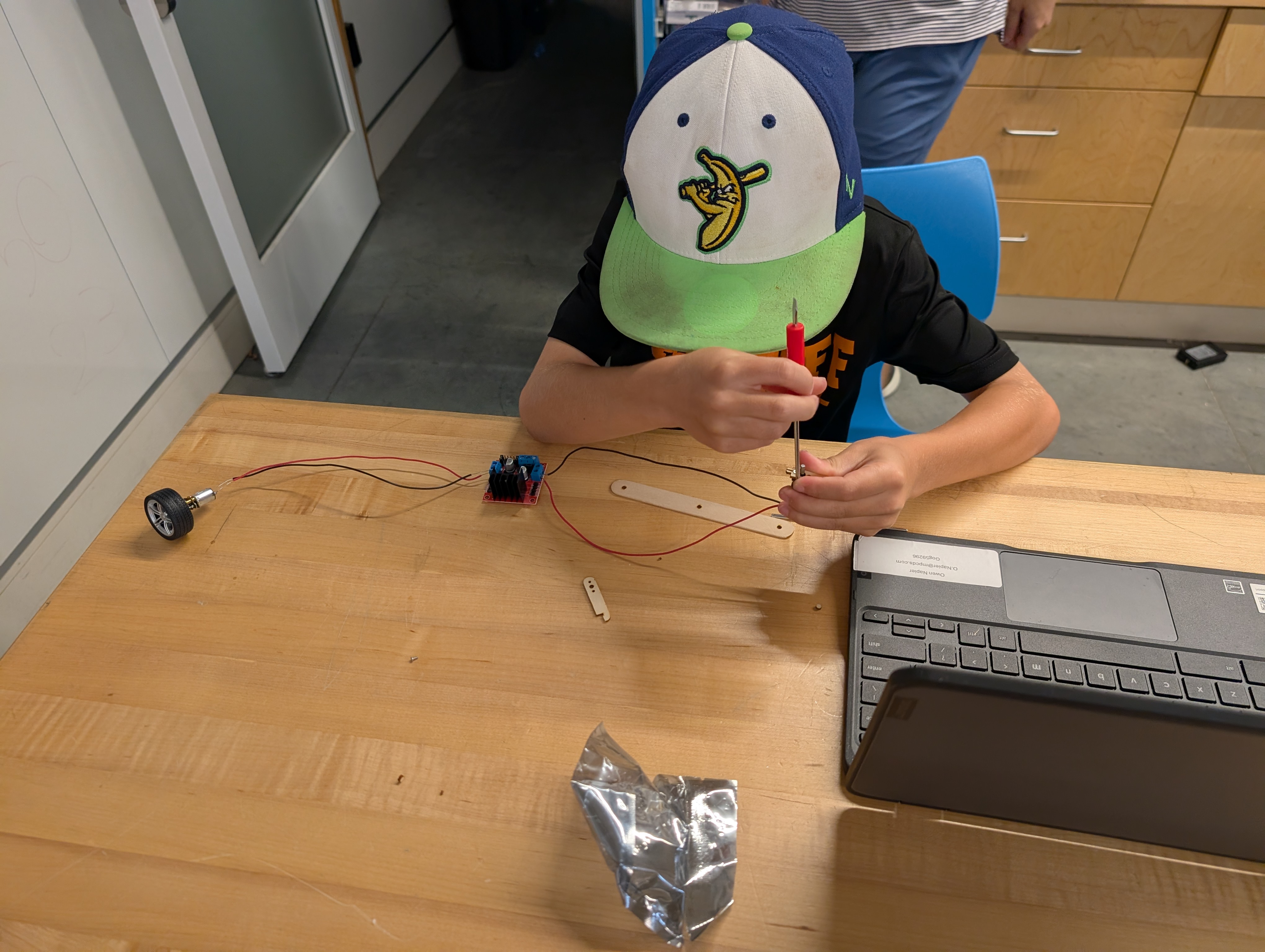
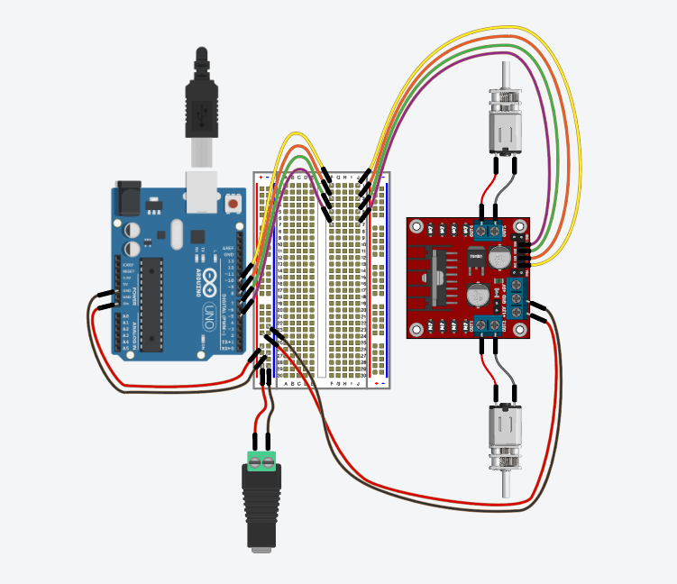
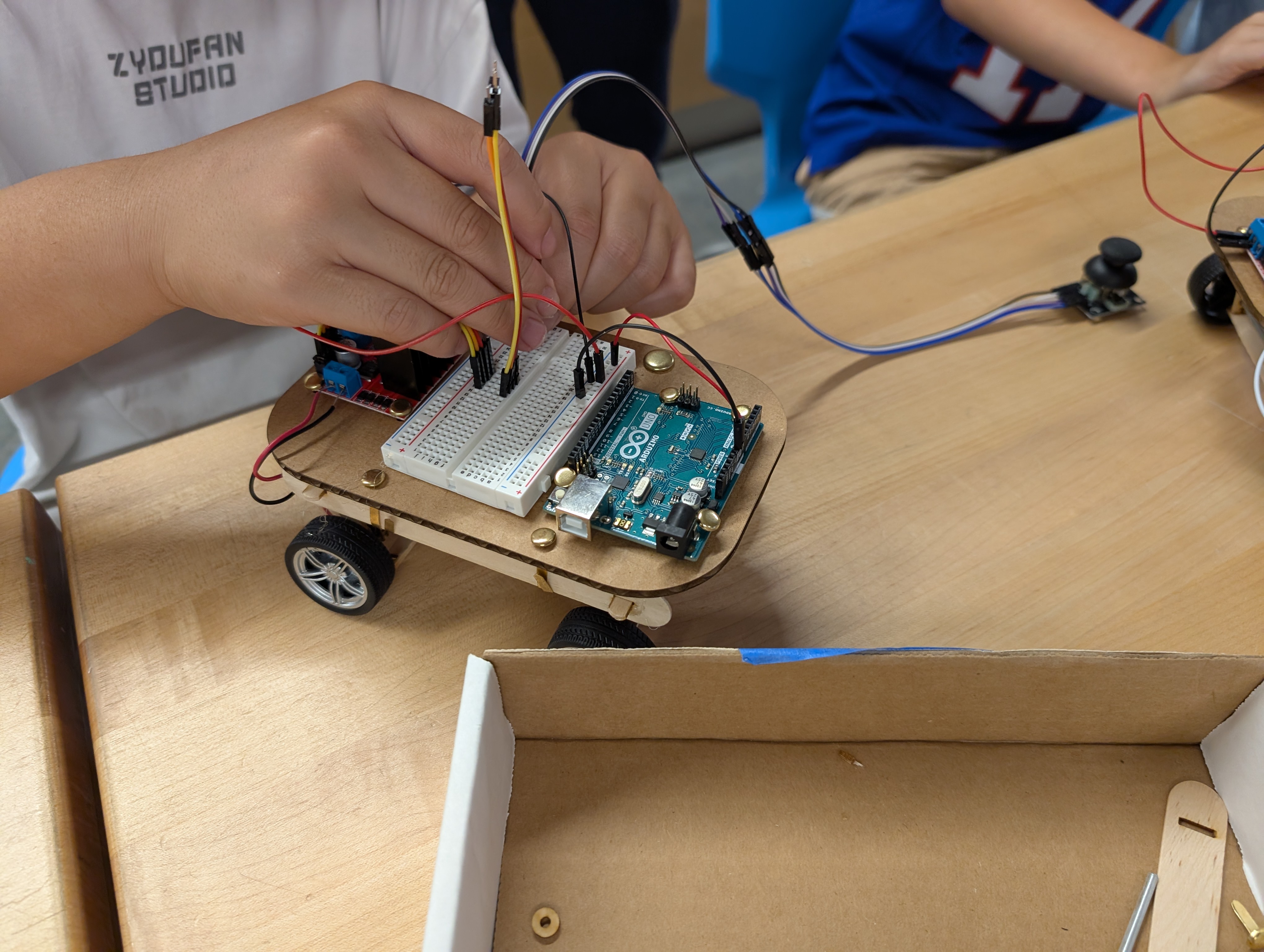
Bringing the circuit parts together... mechanically!
Insert the wires from the motors into the 2-position screw-block terminals on L298N Motor Driver.
Add wires to connect the motor driver to the breadboard power row.
Add wires to connect the motor driver control terminal to the breadboard
Add wires for power supply
The Breadboard used in this diagram may seem superfluous. It is intended to scaffold future lessons, and may be omitted if no other components are expected.
If desired, LED’s and resistors may be included, to fit alongside motor signal wires.
This phase can be inverted with the build phases, if more time for parts is needed. Arduino code for motor driving: includes Halt, Forward, Reverse, Left and Right functions.
Add the following code to an Arduino sketch:
// lights to be included, if used.
int red = 13;
int yellow = 12;
int green = 11;
int blue = 9;

//motor pins
const int in1 = 10;
const int in2 = 8;
const int in3 = 7;
const int in4 = 5;


void setup() {
  // put your setup code here, to run once:
  Serial.begin(9600);
  pinMode(red, OUTPUT);
  pinMode(yellow, OUTPUT);
  pinMode(green, OUTPUT);
  pinMode(blue, OUTPUT);
  pinMode(in1, OUTPUT);
  pinMode(in2, OUTPUT);
  pinMode(in3, OUTPUT);
  pinMode(in4, OUTPUT);

  //ensure the car starts from a halt, to allow user to set it down
  halt(3000);
  //These lines should be varied in order and duration to
  //create the routines the car will move through.
  forward(200);
  left(200);
  forward(200);
  right(200);
  reverse(200);
  halt(200);
  }


void loop() {
       //use the loop only for things that would repeat.
       //In this case, once is probably enough.
  }


void halt(int wait) {
  Serial.println("Full Stop");
  digitalWrite(red, HIGH);
  digitalWrite(yellow, LOW);
  digitalWrite(green, LOW);
  digitalWrite(in1, LOW);
  digitalWrite(in2, LOW);
  digitalWrite(in3, LOW);
  digitalWrite(in4, LOW);
  foreServo.write(90);
  aftServo.write(90);
  delay(wait);
  digitalWrite(red, LOW);
}

void forward(int wait) {
  Serial.println("forward");
  digitalWrite(green, HIGH);
  digitalWrite(in1, HIGH);
  digitalWrite(in2, LOW);
  digitalWrite(in3, HIGH);
  digitalWrite(in4, LOW);
  delay(wait);
  halt(0);
  }

void reverse(int wait) {
  Serial.println("reverse");
  digitalWrite(red, HIGH);
  digitalWrite(in1, LOW);
  digitalWrite(in2, HIGH);
  digitalWrite(in3, LOW);
  digitalWrite(in4, HIGH);
  delay(wait);
  halt(0);
  }

void left(int wait) {
  Serial.println("left turn");
  digitalWrite(yellow, HIGH);
  digitalWrite(in1, HIGH);
  digitalWrite(in2, LOW);
  digitalWrite(in3, LOW);
  digitalWrite(in4, HIGH);
  delay(wait);
  halt(0);
}

void right(int wait) {
  Serial.println("right turn");
  digitalWrite(blue, HIGH);
  digitalWrite(in1, LOW);
  digitalWrite(in2, HIGH);
  digitalWrite(in3, HIGH);
  digitalWrite(in4, LOW);
  delay(wait);
  halt(0);
}
Once the code is complete, compile to check for errors, then upload to the Arduino.
NOTE:
USB power may be insufficient to see real motor movement. Don’t be discouraged, disconnect computer, and use included connector for a battery.
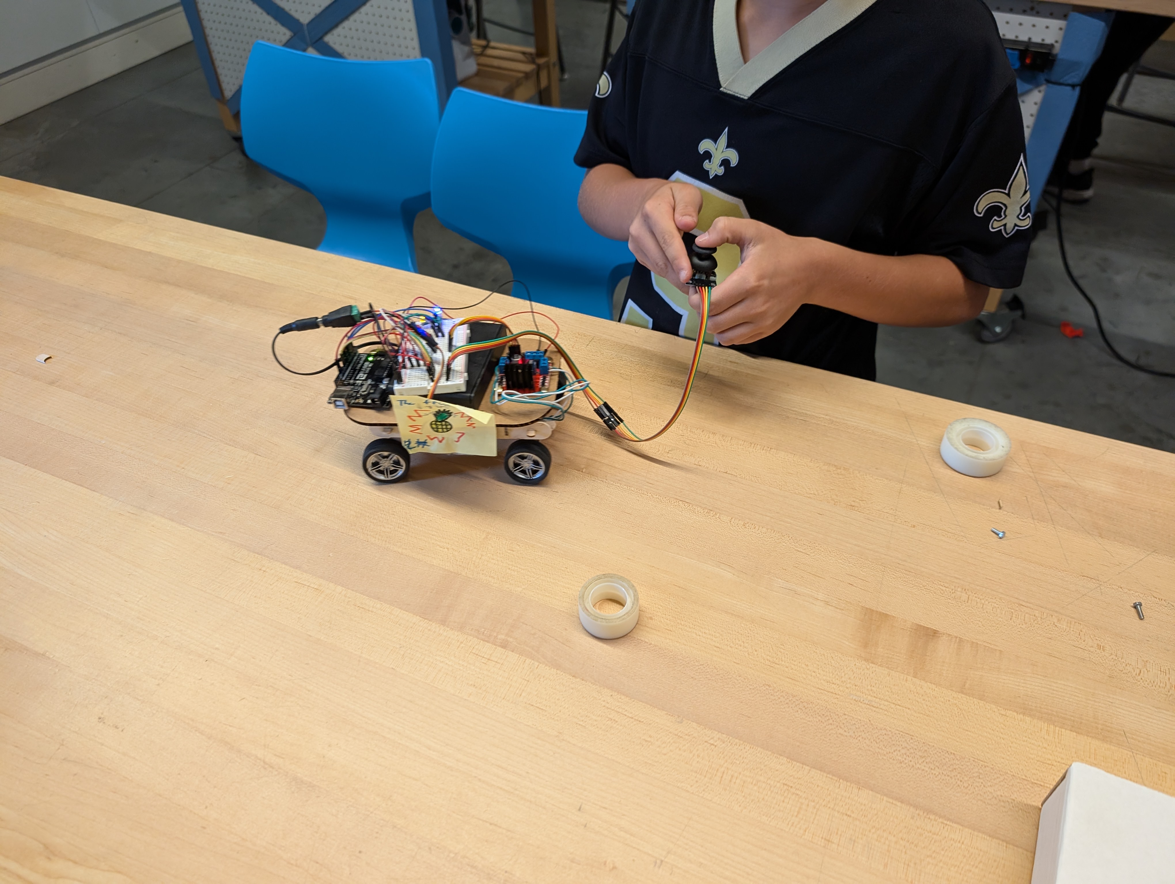
From here, Check your hardware to make sure nothing has been missed. Have someone else look it over as well, then load your code and start watching it move through your shape.
ASSESSMENT!
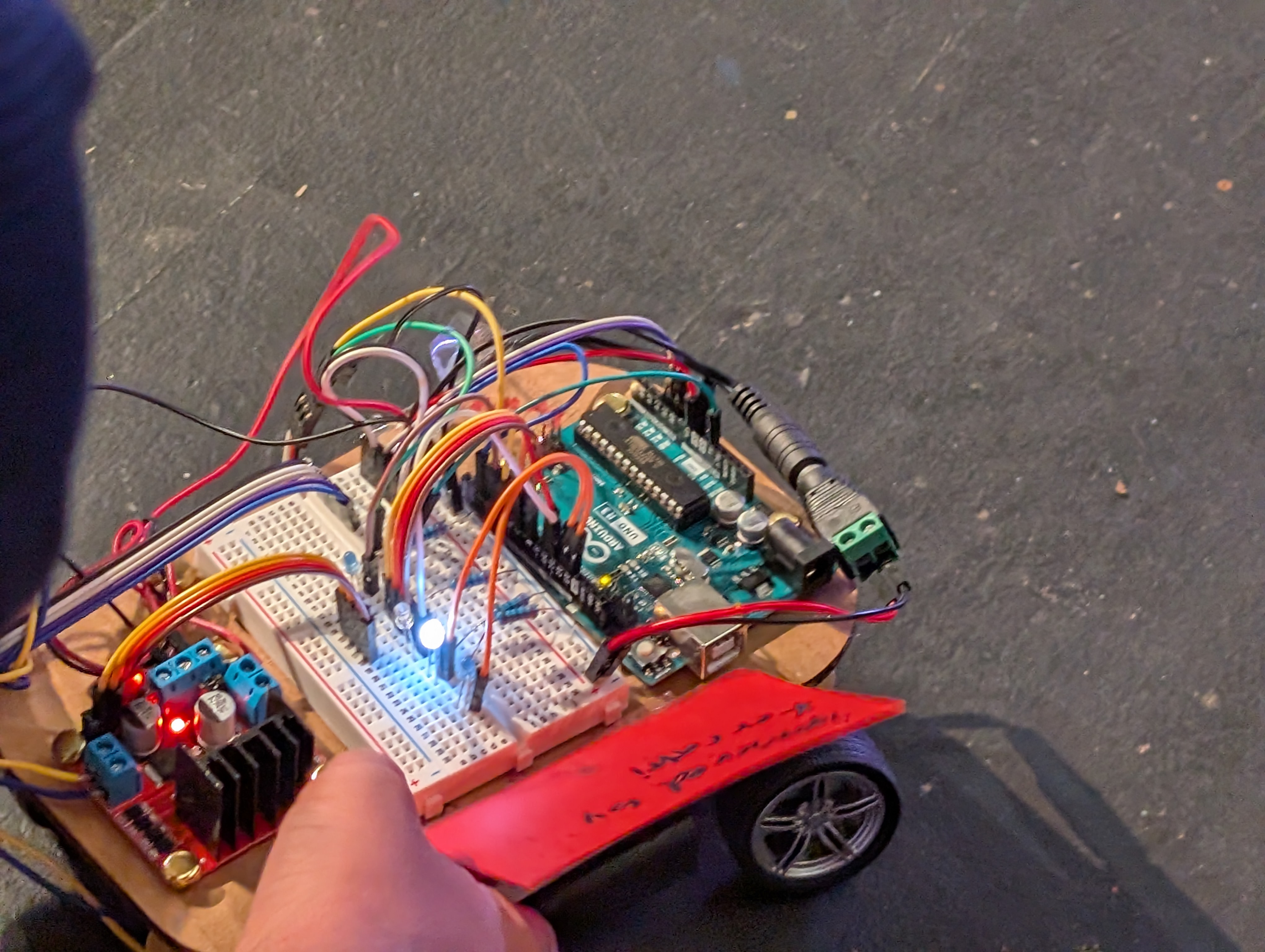
Each vehicle should be visual inspected to ensure that all parts have been assembled correctly, and relevant connections have been joined.
Then, load code if not already complete, and attach power.
Set the bot on a clear open surface, preferably the ground, and let it go.
Take note of the vehicle movements, then discuss with peers:
Having trouble? Let us know by completing the form below. We'll do our best to get your issues resolved quickly.
"*" indicates required fields