- Loading…

This lesson is all about showing grades 9-12 students the essentials of fabrication and programming to create their own unique LED display. The students will be shown how to use basic software features to etch and cut out either glass or clear acrylic. The wooden bases themselves can either be cut out with the laser or from a CNC milling machine, depending on which is more available. During the final steps of assembly is when students learn Arduino programming once they soldered the LED light strip onto a micro controller.

TOOLS/MACHINES
SOFTWARE
MATERIALS
If a wooden base is not already provided by an instructor, use the sizes below to draw out the basic shapes on Vcarve Pro/Aspire to then cut out using our CNC milling machine.
SIZE REQUIREMENTS
Base Size: 5” x 2” x 0.75″
Slot for Sign: 4” Line with a 0.25″ Diameter Milling Bit
Groove for LED Strip: 4.5” x 0.5” (0.6″ deep)
Groove for Arduino Nano (0.375″ deep):

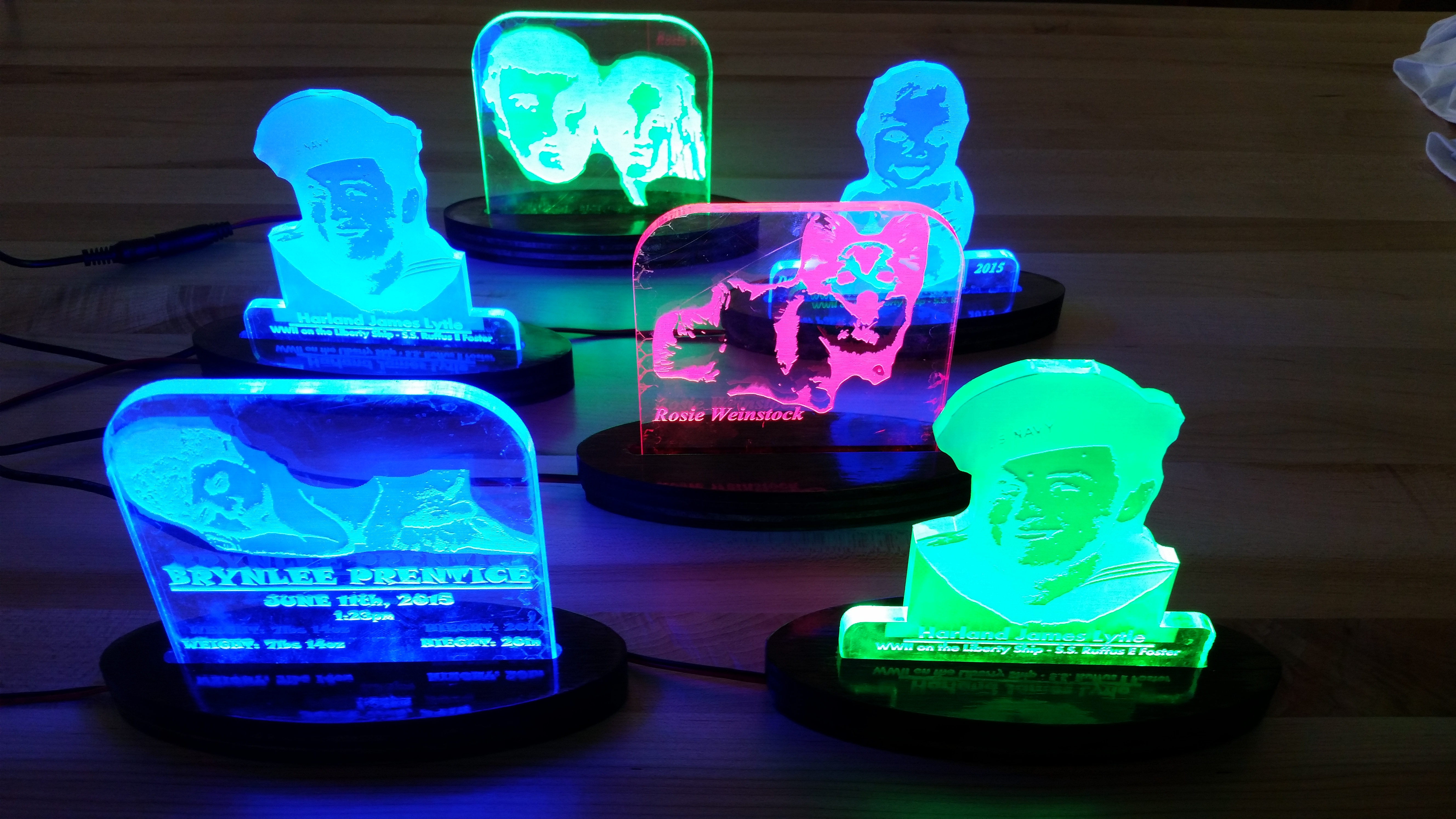
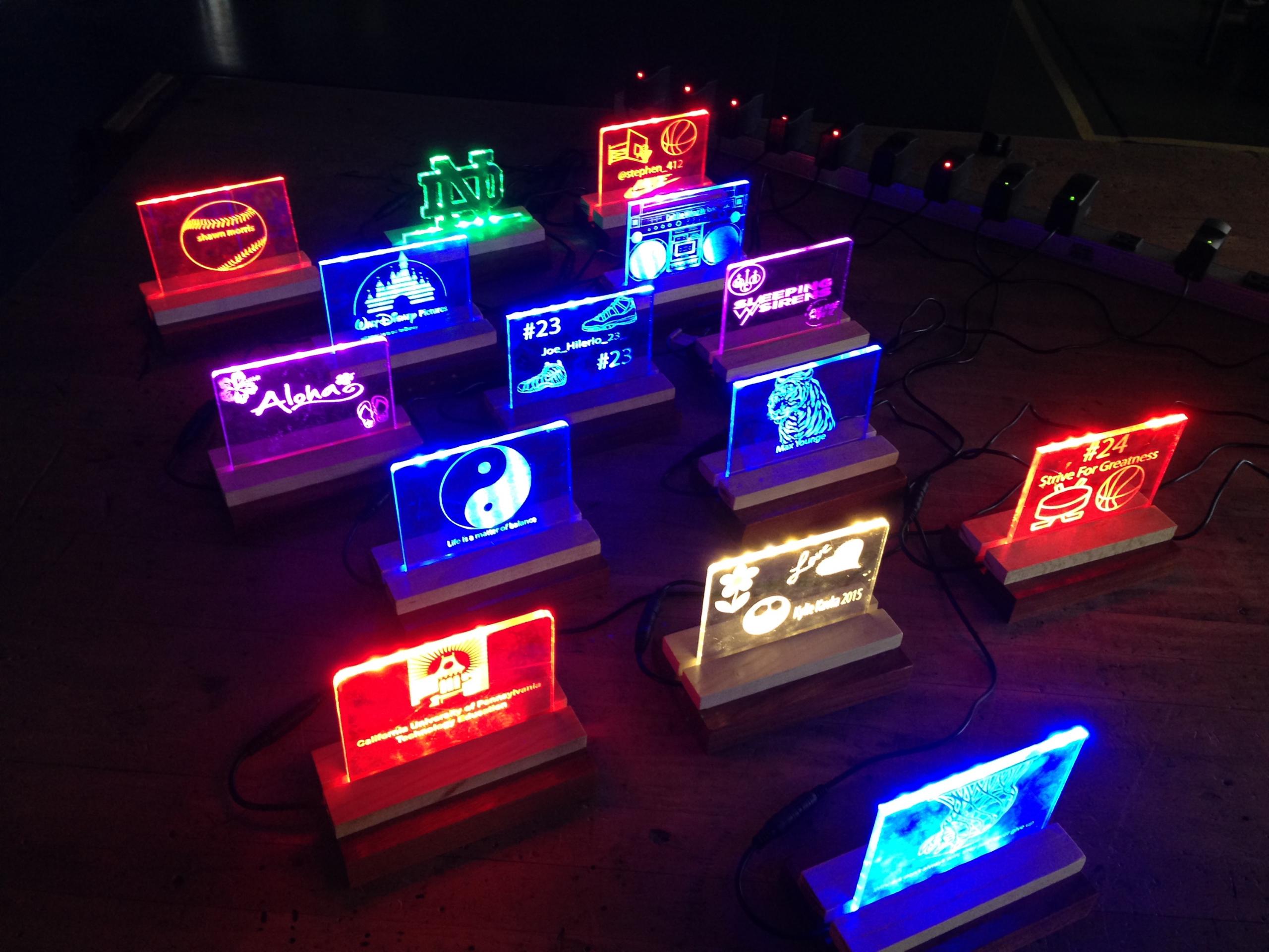
This is the true creative portion of the project. Have the students use the essential design features from a vectoring software (CorelDRAW, Illustrator, Inkscape) to make graphics/text features to laser engrave the glass or plastic. Let the students have plenty of time on this portion so they can really make their design exciting and eye-popping!
As an instructor, make sure to go over the following points when it comes to designing the plastic/glass sign from a vectoring software (CorelDRAW, Illustrator, Inkscape):

All designs are then sent to a laser cutter by either the students or instructor to continue assembling their parts.
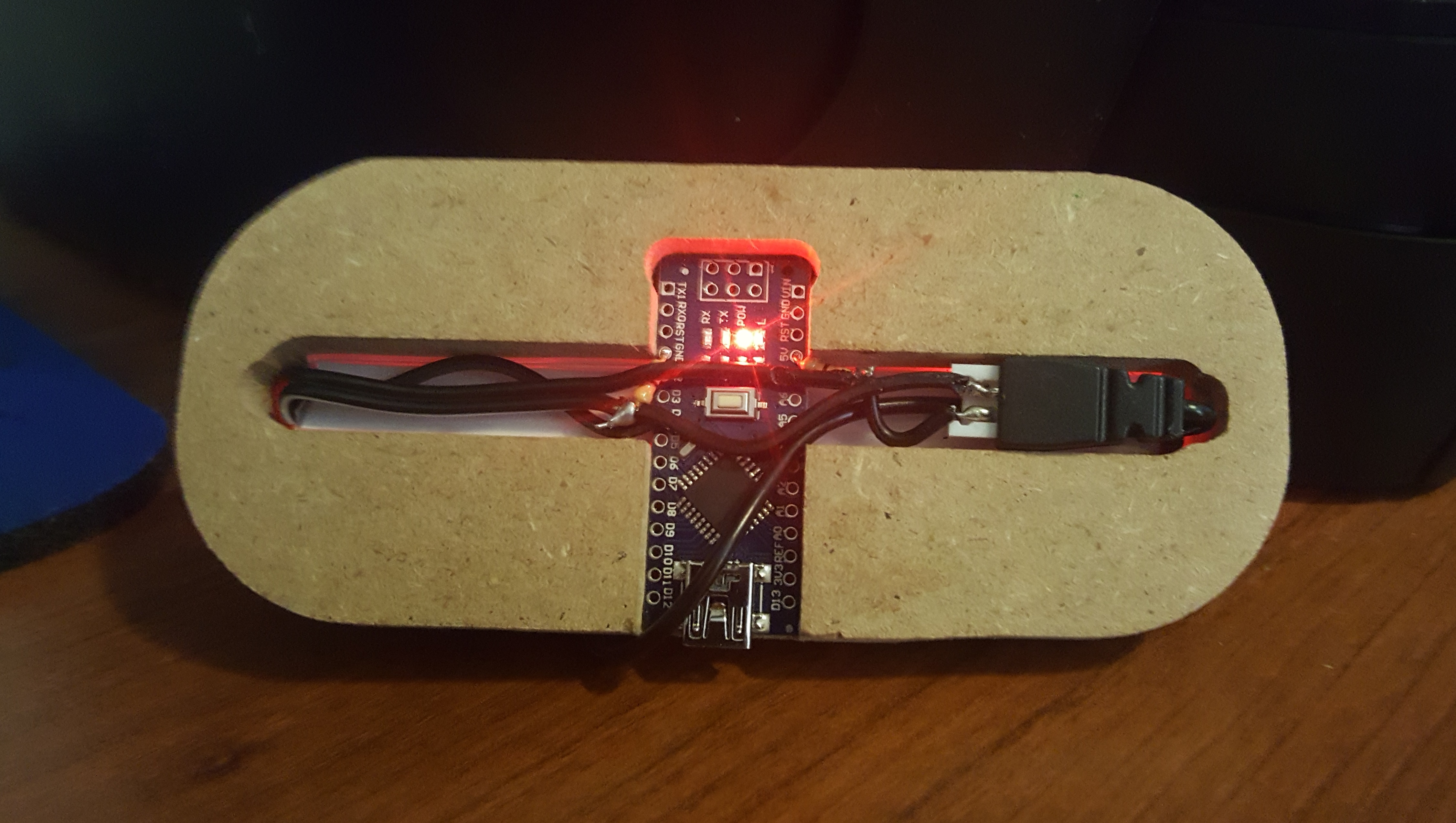
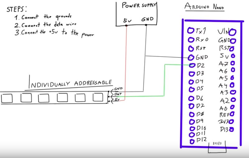
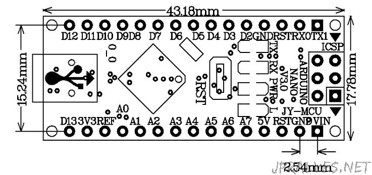
Learn to properly wire the Arduino micro controller (Nano) to a reliable power source to control the RGB light strip.
If the students design is accurate, the Arduino, RGB light strip, and the acrylic/glass sign should all fit snug. Use adhesives available to tweak any of these fittings if needed.
Students can now watch this short Youtube video explaining the connections that will need to be made to properly power both the Individually addressable RGB LED strip, and the micro controller.
https://www.youtube.com/watch?v=QnWZdxMytaA&t=203s

Using the same Youtube link shown in the previous step, students can learn to manipulate code to tweek any LED colors or fade loops they want.

Using the same Youtube link shown in the previous step, students can learn to manipulate code to tweak any LED colors or fade loops they want. It is the job of the instructor to break down the programming language of Arduino C to let the students understand what exactly is happening in the code, examples being:
Down below, you will see an example code I created of the final product that uses a series of For Loops in order to program the LED to transition through every color in the RGB spectrum repeatedly. Simply copy and paste the code into Arduino IDE and make sure the proper libraries are included to run the program. Once students get comfortable with this language, have them create unique transitions of their own to see what they come up with!
#include
#define NUM_LEDS 6
#define LED_PIN 4
CRGB led[NUM_LEDS];
void setup() {
FastLED.addLeds(led, NUM_LEDS);
for (int i = 0; i < NUM_LEDS; i++) {
led[i] = CRGB(0, 0, 0);
}
FastLED.show();
}
void setRed(int val) {
for (int i = 0; i < NUM_LEDS; i++) {
led[i] = CRGB (val, 0, 0);
}
FastLED.show();
}
void setYellow(int val) {
for (int i = 0; i < NUM_LEDS; i++) {
led[i] = CRGB (255, val, 0);
}
FastLED.show();
}
void setGreen(int val) {
for (int i = 0; i < NUM_LEDS; i++) {
led[i] = CRGB (val, 255, 0);
}
FastLED.show();
}
void setTeal(int val) {
for (int i = 0; i < NUM_LEDS; i++) {
led[i] = CRGB (0, 255, val);
}
FastLED.show();
}
void setBlue(int val) {
for (int i = 0; i < NUM_LEDS; i++) {
led[i] = CRGB (0, val, 255);
}
FastLED.show();
}
void setPurple(int val) {
for (int i = 0; i < NUM_LEDS; i++) {
led[i] = CRGB (val, 0, 255);
}
FastLED.show();
}
void setWhite(int val) {
for (int i = 0; i < NUM_LEDS; i++) {
led[i] = CRGB (255, val, 255);
}
FastLED.show();
}
void setEnd(int val) {
for (int i = 0; i < NUM_LEDS; i++) {
led[i] = CRGB (255, val, val);
}
FastLED.show();
}
void loop() {
for (int i = 255; i < 256; i++) {
setRed(i);
delay(10);
}
for (int i = 0; i < 256; i++) {
setYellow(i);
delay(10);
}
for (int i = 255; i > 0; i–) {
setGreen(i);
delay(10);
}
for (int i = 0; i < 256; i++) {
setTeal(i);
delay(10);
}
for (int i = 255; i > 0; i–) {
setBlue(i);
delay(10);
}
for (int i = 0; i < 256; i++) {
setPurple(i);
delay(10);
}
for (int i = 0; i < 256; i++) {
setWhite(i);
delay(10);
}
for (int i = 255; i > 0; i–) {
setEnd(i);
delay(10);
}
}
Having trouble? Let us know by completing the form below. We'll do our best to get your issues resolved quickly.
"*" indicates required fields