- Loading…
How can you combine electronics, chemistry and sewing in a single activity? By sewing a smart crystal lamp! You need to use a needle and thread to stitch the electronic components, code an Arduino microcontroller to make your lamp responsive to temperature and finally decorate it with home-grown aluminium crystals. Ready?
• Thin light-coloured felt (22 cm x 10 cm, 1 mm thick)
• Vinyl glue
• Conductive thread
• Needles
• 12 Neopixel LEDs (2 spares)
• Arduino UNO + USB cable
• Power supply cable for Arduino 6-10V
• Power supply cable for the LEDs 5V 2A
• Wire stripper
• 2 Mammut clamps
• Temperature sensor TMP36
• 10 male – male jumper wires (3 spares)
• 1 small breadboard
• Soldering irons + solder
• Transparent nail polish
• Paper frame Openframe
• Computer
• Potassium alum (700 g)
• Pastic basin 25 cm x 15 cm x 5 cm (about)
• Double-sided tape
• Superglue
Sew the Neopixels
1. Take a 22 x 10 cm piece of felt. Leave 3 cm margin on each side, and with a marker, make a grid of
10 dots, with each dot at a distance of 4 cm from the previous one.
2. Use the vinyl glue to stick 10 Neopixel LEDs on the reference grid. Refer to the drawing below for the orientation of the LEDs so that they are positioned in parallel. In each row, the plus signs should
be on the same side and the minus on the opposite side. This way, all the little arrows will point in the same direction. In the second row, this pattern will be reversed.
3. Connect all the + terminals. Cut about 1.5 m of conductive thread, and thread a needle. Make a knot to fix the thread to the felt piece and pass the thread through the + terminal 3-5 times. Once the connection is strong, continue with the next LED and connect all the + ends. If the thread is not long enough, pass the thread through the + terminal of the last LED, make a knot in the felt and cut the thread. Start the procedure again from the same LED to make sure that the two threads are tightly bound.
4 . Connec t a l l t h e minus terminals. Follow the same steps as in point 3. Be careful never to
cross or touch the thread connected to the plus terminals.
5. After all the + and – terminals are connected in parallel, you have to connect adjacent LEDs to each other in a series. Cut a small piece of thread. Tie one end of the thread to the data terminal of one LED and the second end to the data terminal of the adjacent LED. Pair all the LEDs in this way (see diagram
below).
Complet the circuit
1. Begin by connecting to the ground. Connect the – pin of the LED series to the Arduino GND with a jumper wire. To make a soft-hard connection, insert the jumper wire into the minus pin of
the LED first and solder. Now, use another jumper wire and a mammut clamp to connect to the
– pin of the LED series to the – w i re of the power supply. Preferably choose an LED at the
centre of the grid (e.g. the 5th LED) to make sure that the electricity is evenly distributed
over the circuit. To make a softhard connection, insert the jumper wire into the – pin of the
LED first and solder it. Note that the two jumper wires should be connected from the back of the felt piece. The ground of the temperature sensor should be connected to the Arduino GND through a
breadboard and a jumper wire.
2. Both the temperature sensor and the pixel work well with 5V power; however, the LEDs series
needs about 2 A (see box below), which the Arduino cannot provide. An external power supply is therefore needed. Connect the + pin of the sensor to the Arduino board as shown in the scheme below (5V pin on Arduino). Connect the + pin of the LEDs series to the + wire of the power supply with a mammut clamp. Again, choose an LED in the centre (the 5th) to make sure t h e e l e c t r i c i t y i s e v e n l y distributed over the circuit. For a soft-hard connection, insert the jumper wire into the – pin of the LED first and solder it. The jumper wires should be connected from the back of the
felt piece. Power the Arduino Board with 6 – 1 0 V u s i n g a USB c a b le connected to a computer.
3. Attach the input (middle leg of the sensor) to the analog pin A0 of the Arduino board (see
d r a w i n g ) t h r o u g h t h e breadboard.
4. Attach the output (middle pin of the LEDs) to digital pin 2 of the Arduino board with a
soldered jumper wire (as for the + and -). Be careful: pin 2 should be connected to the first LED, not
any LED ! For a full description of the wiring and power supply, please refer to the Adafruit Neopixel
U b e r g u i d e ( h t t p s : / /learn.adafruit.com/adafruitneopixel-uberguide/poweringneopixels).
How to code the Arduino
To program the Neopixels, first install Adafruit_NeoPixel via Library Manager. After having connected and powered the circuit, test the example codes contained in the library.
For a full description of how to install and connect an Arduino board,
please refer to Getting Started with Arduino Uno (https://
www.arduino.cc/en/Guide/ArduinoUno).
For a full description of how to install the Arduino Library, please refer to Arduino Library Installation (https://learn.adafruit.com/adafruitneopixel-uberguide/arduino-library-installation).
The code to control the LEDs is quite simple: depending on the temperature range, the LEDs will change colours. In the variable section, we defined the output pin for the LEDs (2), the number of LEDs (10), the brightness (50), the input pin for the sensor (A0) and called the libraries.
The Void Setup section, which runs when the program begins, lays the foundation for the actions executed later in the program. The input and output are defined here. After the setup section runs, the loop section runs over and over until the Arduino is turned off. The first part of the code is for the temperature sensor. You can read the temperature in degrees Celsius on the Arduino serial monitor to test if it works fine.
The second part of the code is also simple: it tells the LEDs to change colour for every variation of 0.5 degree Celsius. You can choose the colours you prefer and set bigger or smaller temperature fractions. Remember to close the code with a curly bracket. Test your circuit and code before moving to the next step.
How to grow crystals on your circuit
1. Coat the conductive threads and LEDs with transparent nail p o l i s h t o p r e v e n t t h e c o n n e c t i o n s f rom b e i n g corroded by the crystals. Coat both sides of the felt. .
2. Dissolve 700 g of alum in 1 litre of hot water. Once the alum is completely dissolved and the
solution is supersaturated, pour it into a plastic basin.
3. Immerse the felt with the circuit into the solution with the LED side facing down. Do not move the basin for at least 24 hours.
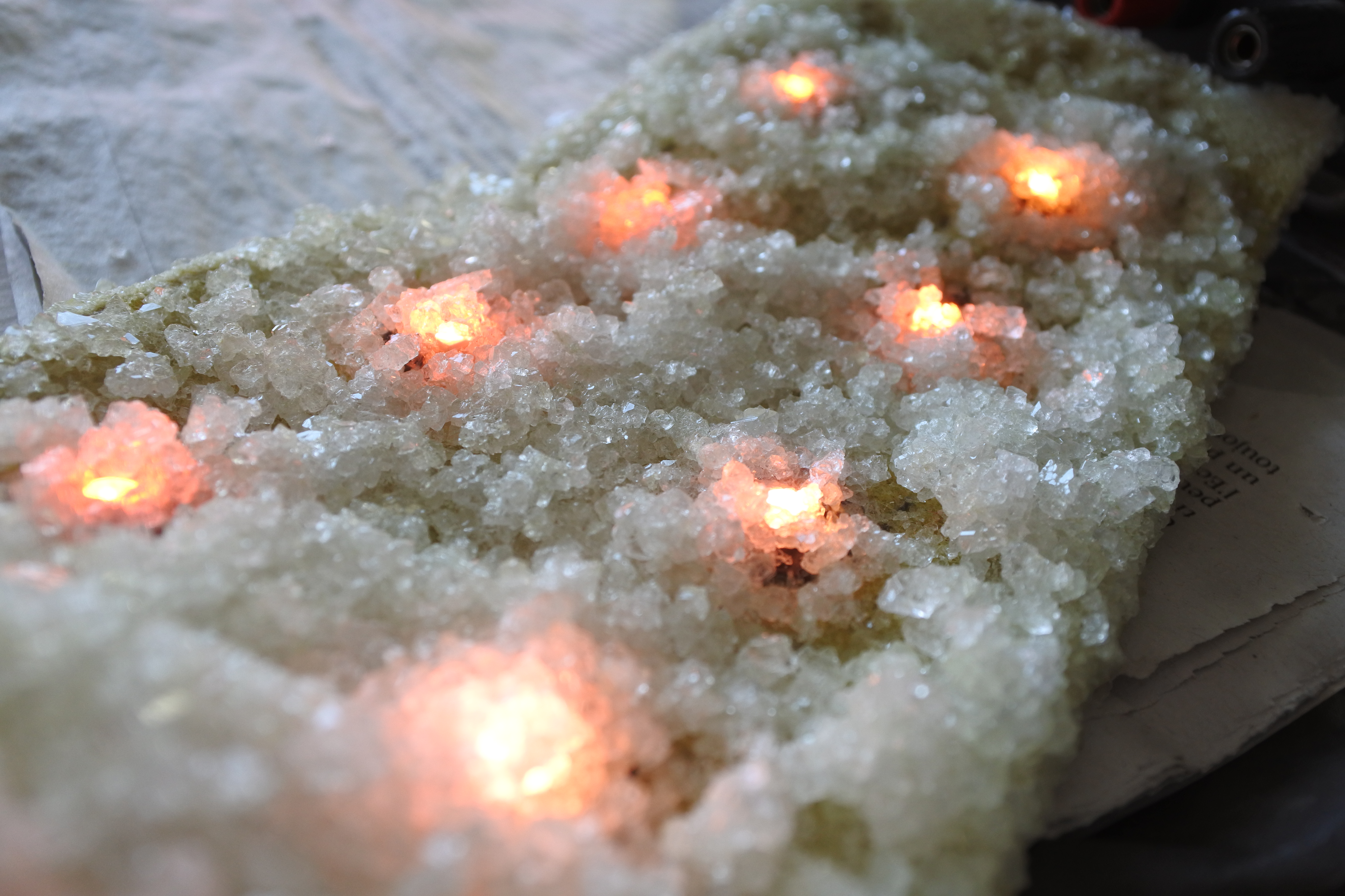
4. After 1-3 days, remove the felt and let it dry: Eventually, the crystals will grow and be strongly bound to the LED layer. The felt will be covered by a layer of 2-3 mm of crystals.
How to assemble the lamp
1 . Once t h e s t r u c t u re i s completely covered with crystals, p r o c e e d w i t h t h e f i n a l
attachments.
2. In the centre of the paper frame, cut out a rectangle of 18 cm x 8 cm and stick the felt to the frame with a strong glue.
3. With double-sided tape, fix the Arduino and the breadboard with the temperature sensor to the interior of the box, as shown below.
4. Gently close the box and if needed tape it to keep it closed.
5. Switch on the power supply of the LEDs first and then of the Arduino.
6. Power the Arduino by plugging in the power supply or the USB cable to the computer.
Your lamp is ready!
Having trouble? Let us know by completing the form below. We'll do our best to get your issues resolved quickly.
"*" indicates required fields
Thank you for your fab contribution!
I would love to see some photos of this project!
Dear Liz, thanks for your message! Could you please send me a message to [email protected]?
I will send you some photos and give you more details. My best regards
Cristina