- Loading…
Using CAD software, principles of mechanical power transmission and Digital Fabrication tools, students will be able to calculate, design and manufacture a piece of the gear system.

Materials:
Theoretical explanation of mechanical transmission, gears and speed ratio.
What is mechanical transmission?
It is a way to transmit mechanical energy between rigid solids.
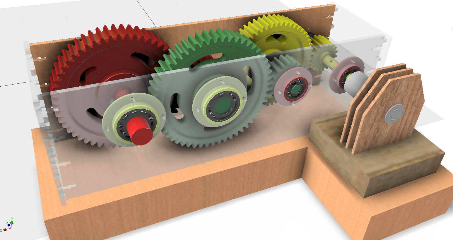
What is a gear train?
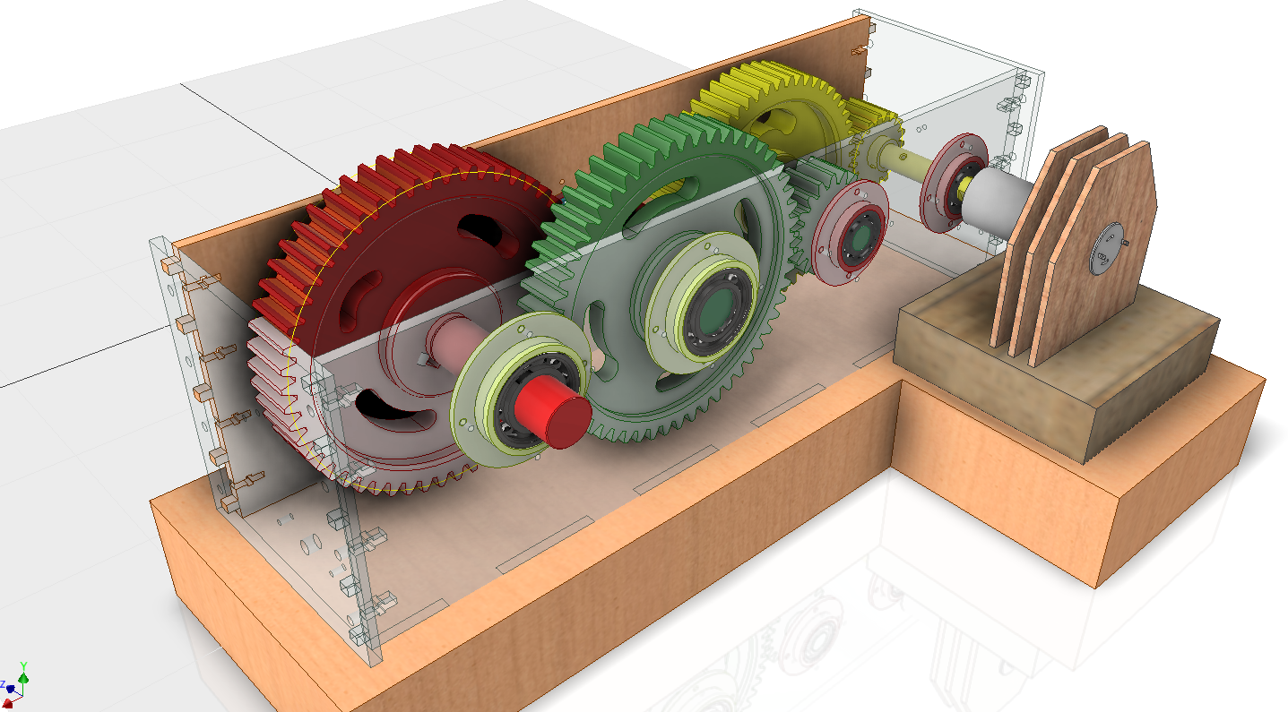
It is a type of mechanical transmission that uses gears to connect two rotating shafts, the input shaft rotates at high speeds but has low torque; however, the output shaft rotates at a lower speed but its torque is higher. Our speed reducer is a gear train.
Gear definitions
m = D/N = P/𝜋
Do = D + 2m
Speed ratio
Relation between the speed and number of teeth of an input gear (pinion) and an output gear (gear).
k = nP/nG = NG/NP
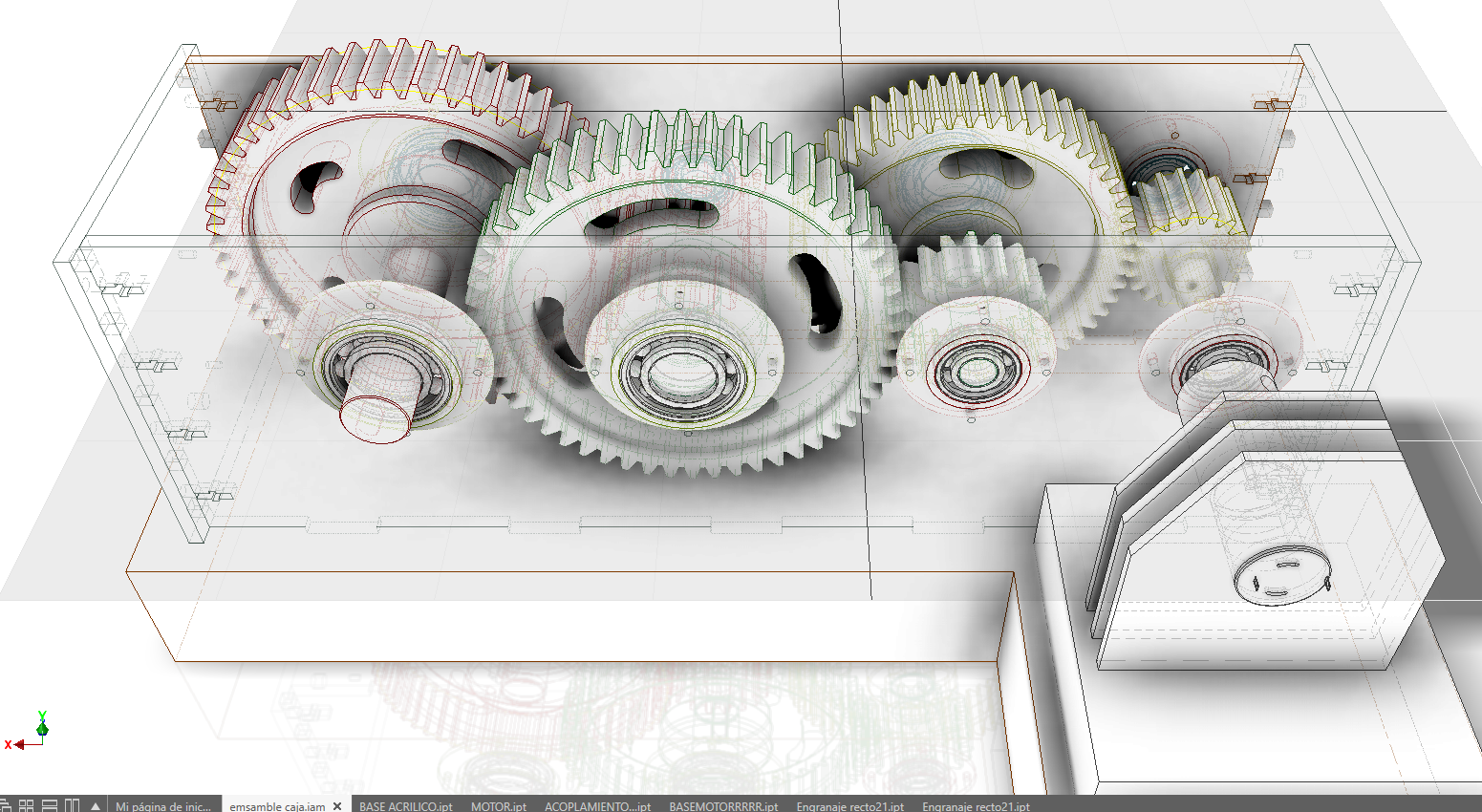
3D modelling of the missing gear and its shaft according to measurements and required calculations.
Teeth number calculation
We know that the desired speed ratio (k) is 3. Also, we can count the pinion’s number of teeth (NP), as it is part of the already assembled reduction system, it is 18. Therefore, the participants can calculate the number of teeth of the final gear (NG), it will be 54.
Module calculation
The participants need to measure the outside diameter of the final gear as it will be already fabricated, it will be around 140mm. If we know NG, we can easily arrive to a formula between m and Do, the participants have to deduce it. Using that formula we calculate m, it will be around 2.5. But the value of m is standardized, therefore we conclude that m is 2.5.
3D Modelling
In Fusion 360, we can use an Add-in to generate our gear, it is called SpurGear. There, we need to introduce our calculations. The gear width can be measured, it should be 24mm.
The gear will be fabricated using layers and pins, then, the gear needs some rectangular holes of 4x8mm. The pins will be rectangles of size 24x8mm.
The gear will be mounted around a shaft, its diameter is 25mm and its length can be measured from the other ones. Pay attention to your 3D printer tolerance.
Between the gear and the shaft, a key will be used, then a keyseat has to be added.
The key is a rectangle of 24x8mm.

Generation of a dxf file from the gear and a stl file from the shaft.
Laser cut files
In Fusion 360, we can export a face of the gear as a dxf file. We can open that file using vector graphics software, usually, laser cut machines use CorelDRAW.
Now, we need to calculate how many layers of MDF will be needed. The participants know that the gear width is 24mm and our MDF´s width is 4mm, therefore they can calculate the number of layers, it is 6.
The last step is to replicate the gear face (in CorelDRAW) 6 times and organize it, in order to minimize the required space. You now have a fabrication plan.
3D printer files
From Fusion 360, the shaft and the key can be directly exported as STL. After doing it, you should be able to open your file using your 3D printer software. If not, there must be an error with your procedure, check for errors.
Using a laser cut machine and a 3D printer, the final gear and its shaft will be fabricated.
Laser cut
First, you have to modify the width of the vectors used in your fabrication plan. Generally, it is 0.01mm.
Depending on your laser cut machine, you may have to modify the color, too.
In order to use the machine, 3 parameters are used: power, speed and frequency. The instructor must show and explain the required values to optimize the cut operation.
Almost every machine’s Z axis must be calibrated, the instructor should perform this procedure.
Finally, we are ready to laser cut the gear’s layers.
3D printer
There are many 3D printers available but all of them have main parameters than can be configured: infill, layer height, shells and raft. The instructor should explain each one.
Now you just have to 3D print your shaft and key.
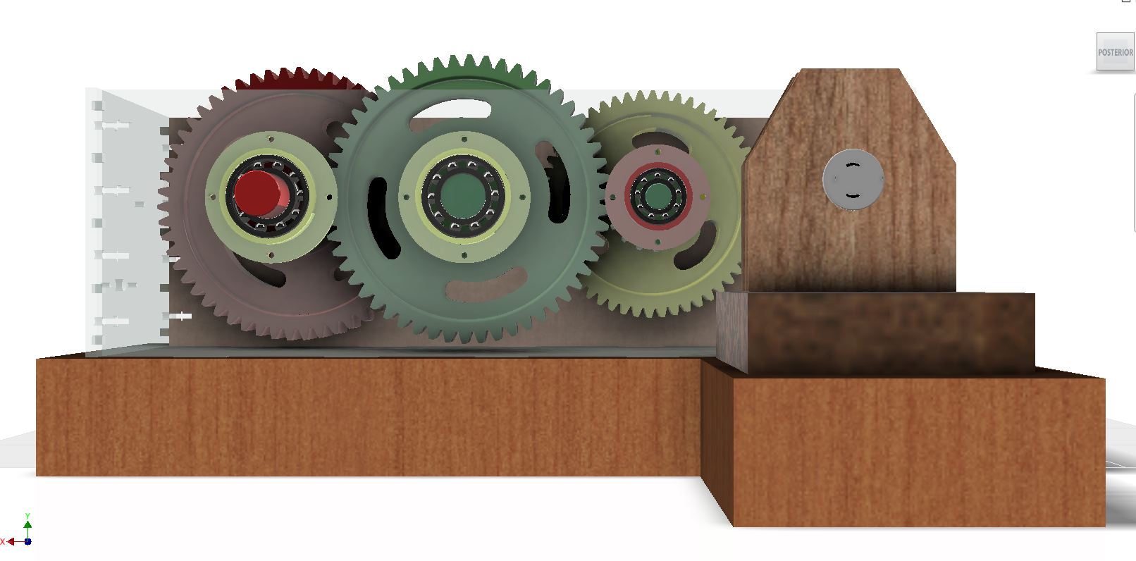
Glue the gear’s layers, align them using pins and mount it over the shaft and the structure.
First, all 6 layers will be glued and stacked. The pins will be inserted immediately. The gear needs to be pressed.
Then, the gear will be mounted on the shaft using the key.
Finally, the shaft will be mounted on the structure using the bearings.
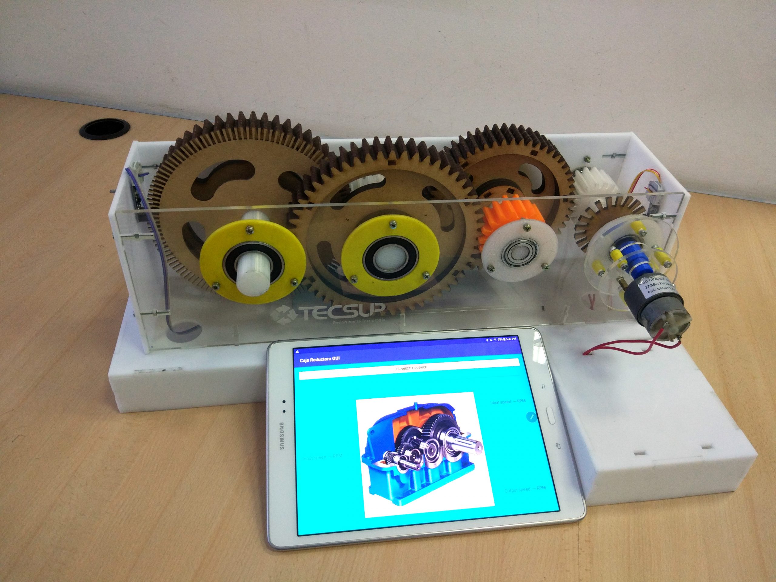
Using the Android app, the value of the speed ratio should be verified.
After the assembly, the speed reducer should be working without errors. The application has to be launched. There, the speed of the first and last gear are shown. Also, the speed ratio of the whole gear train is calculated there. If its value is 27, the gear design and fabrication was successful.
Having trouble? Let us know by completing the form below. We'll do our best to get your issues resolved quickly.
"*" indicates required fields


