- Loading…


As educators, we frequently observe students’ need to confirm that their work aligns with the parameters and expectations established by the teacher. However, these interruptions—particularly during center-based activities—often become disruptive due to the high demand for attention.
To address this challenge, A group of teachers and me designed a traffic light system that allows students to communicate their needs effectively: indicating when they require guidance, when they have completed their work, and when they are working independently at an appropriate pace by switching the lights.
Note: In this case the teachers were my students.
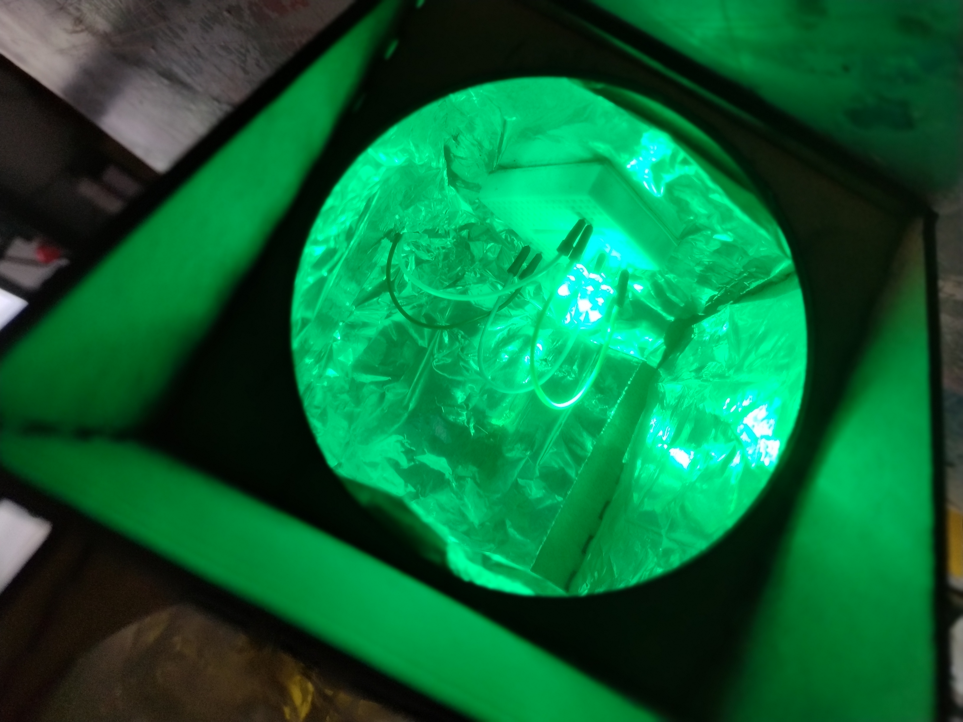


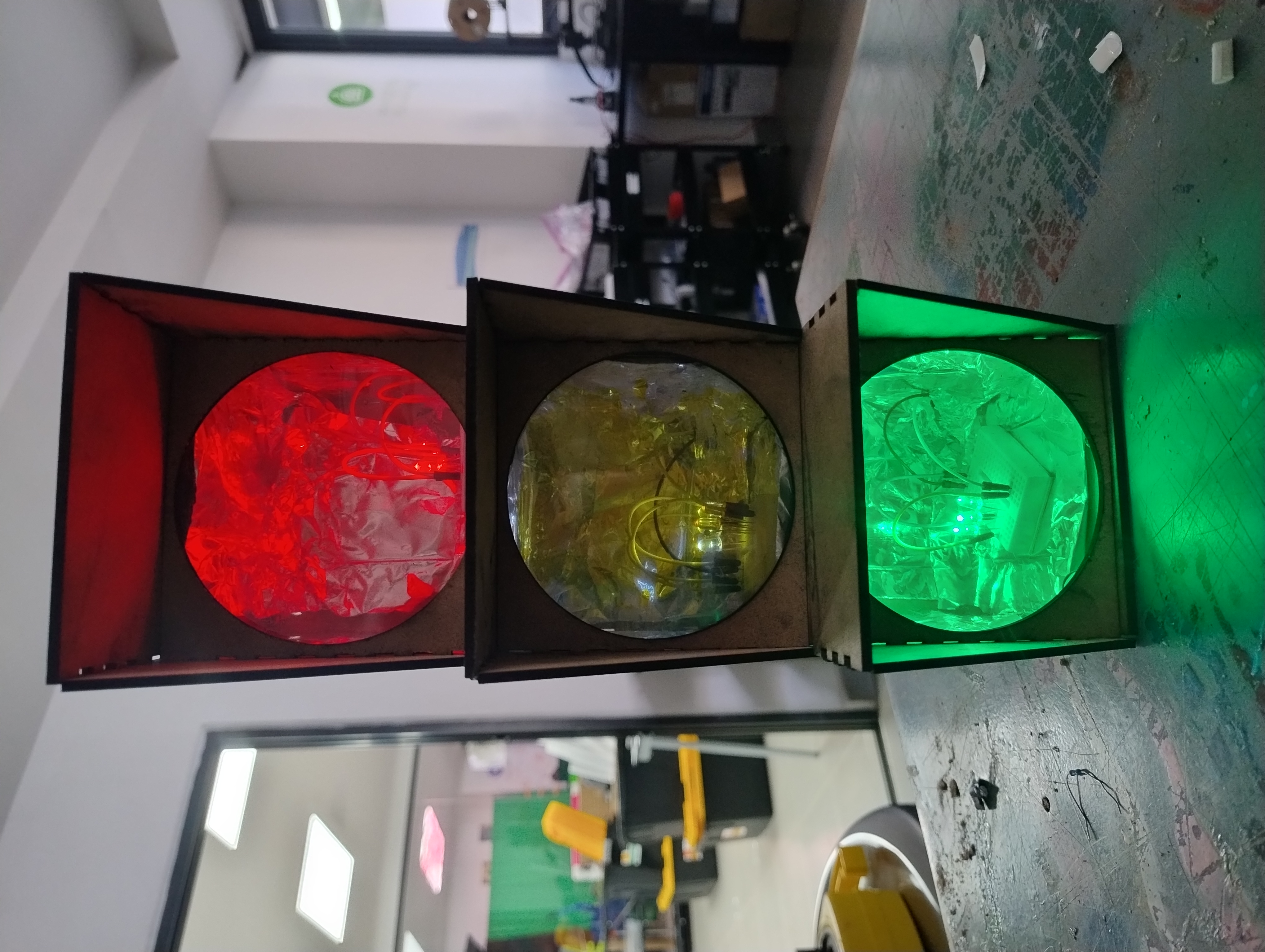
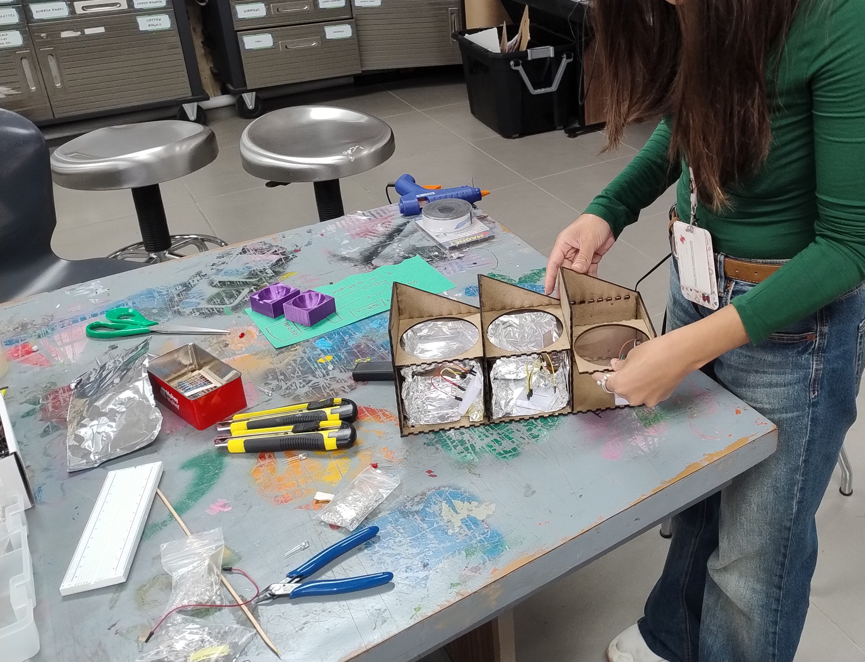
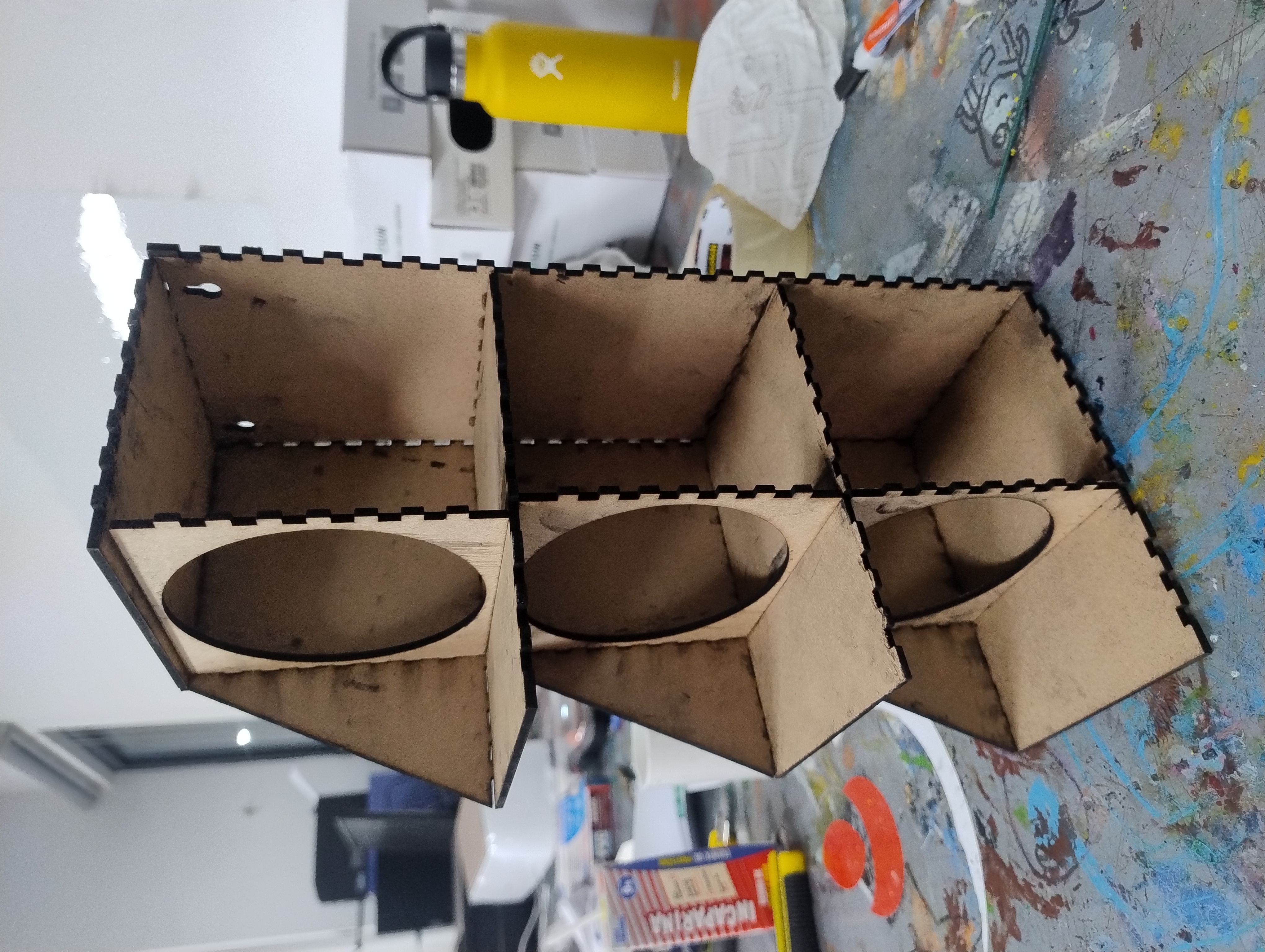
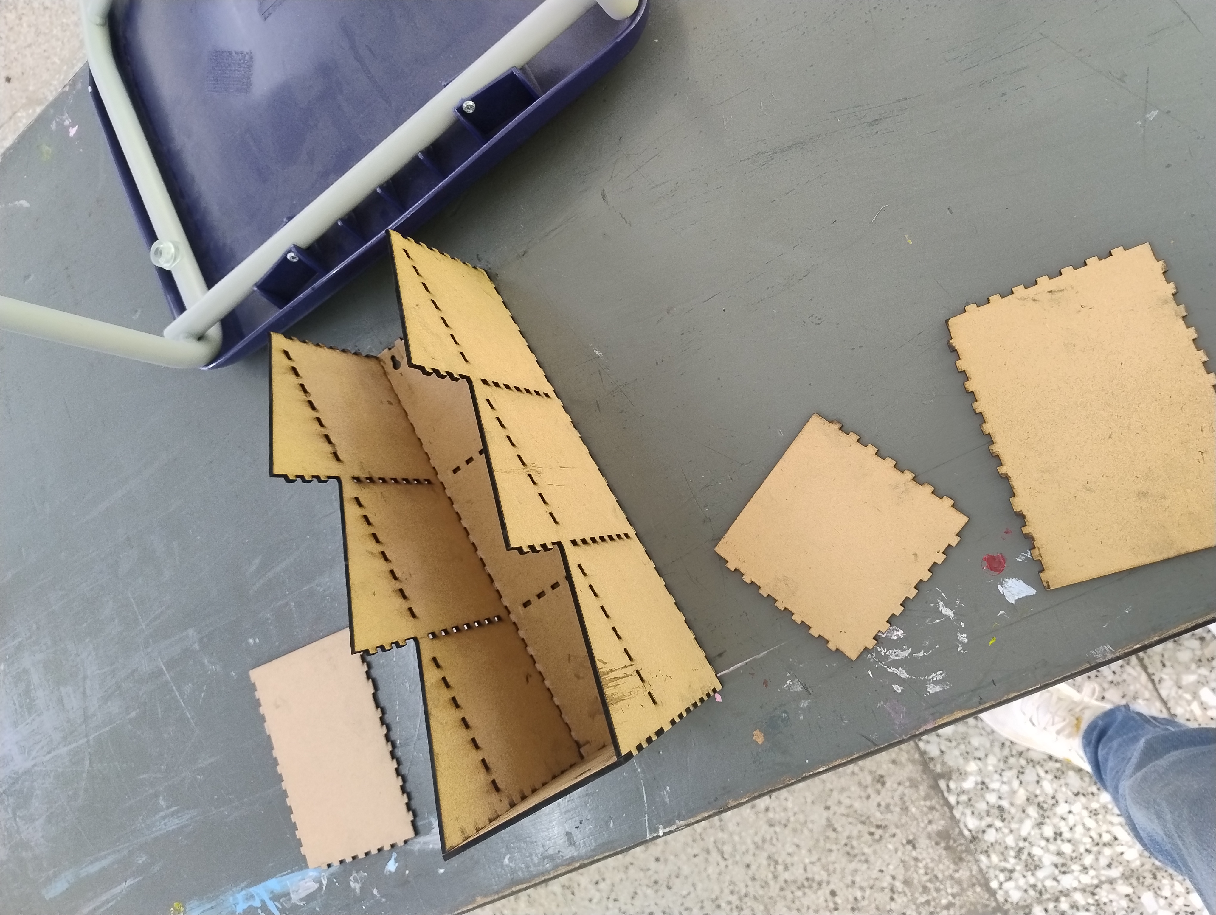
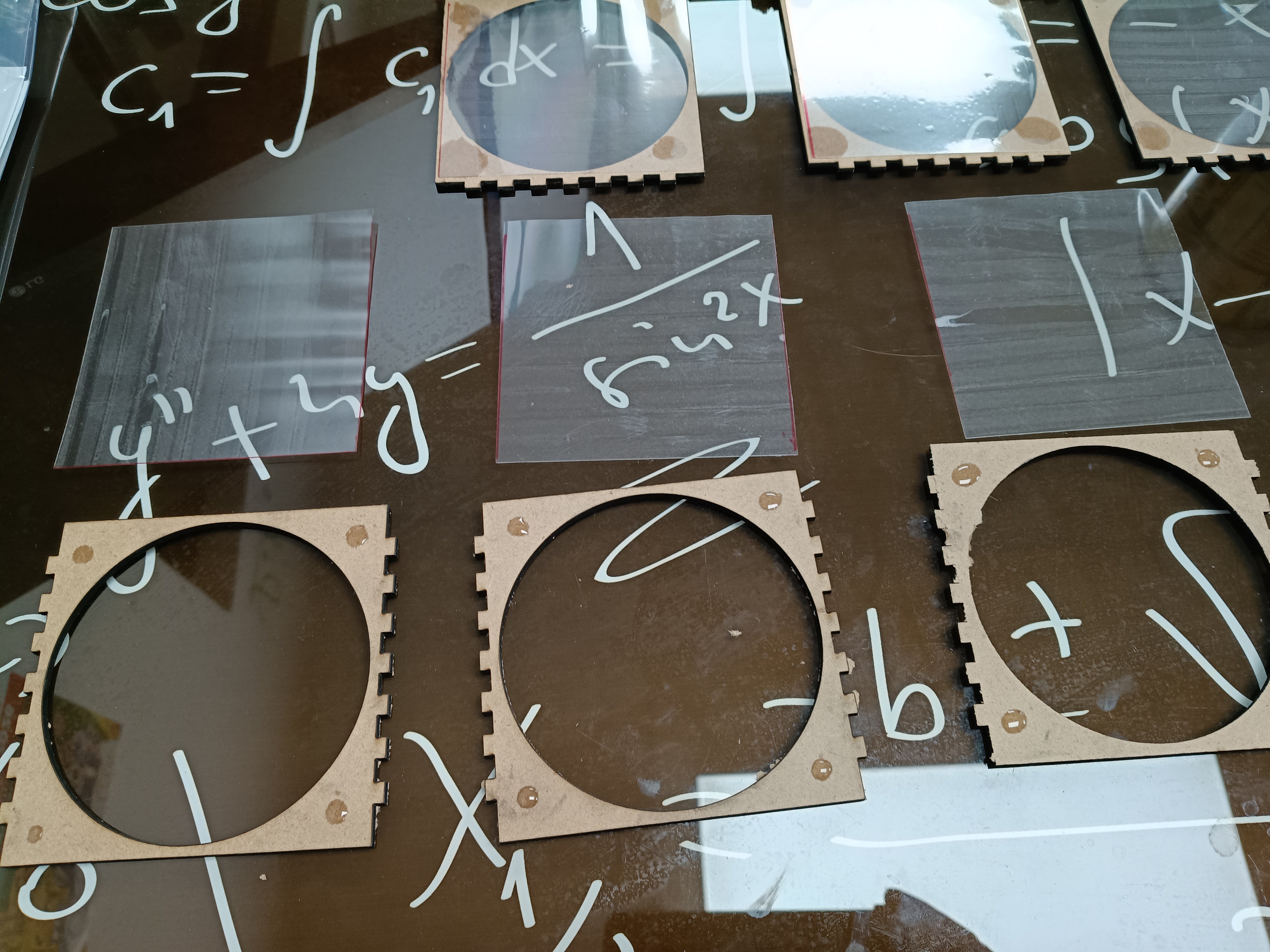
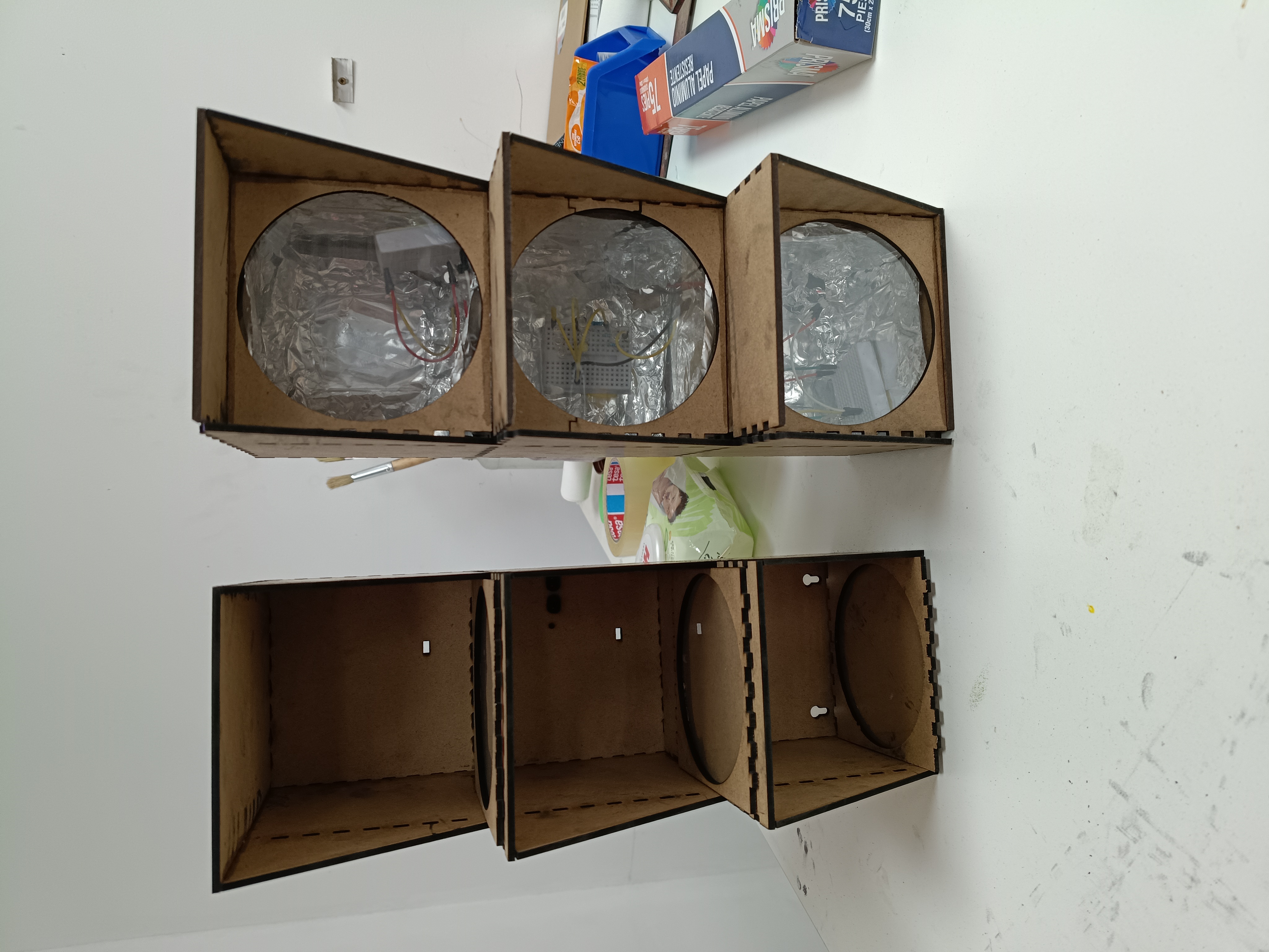
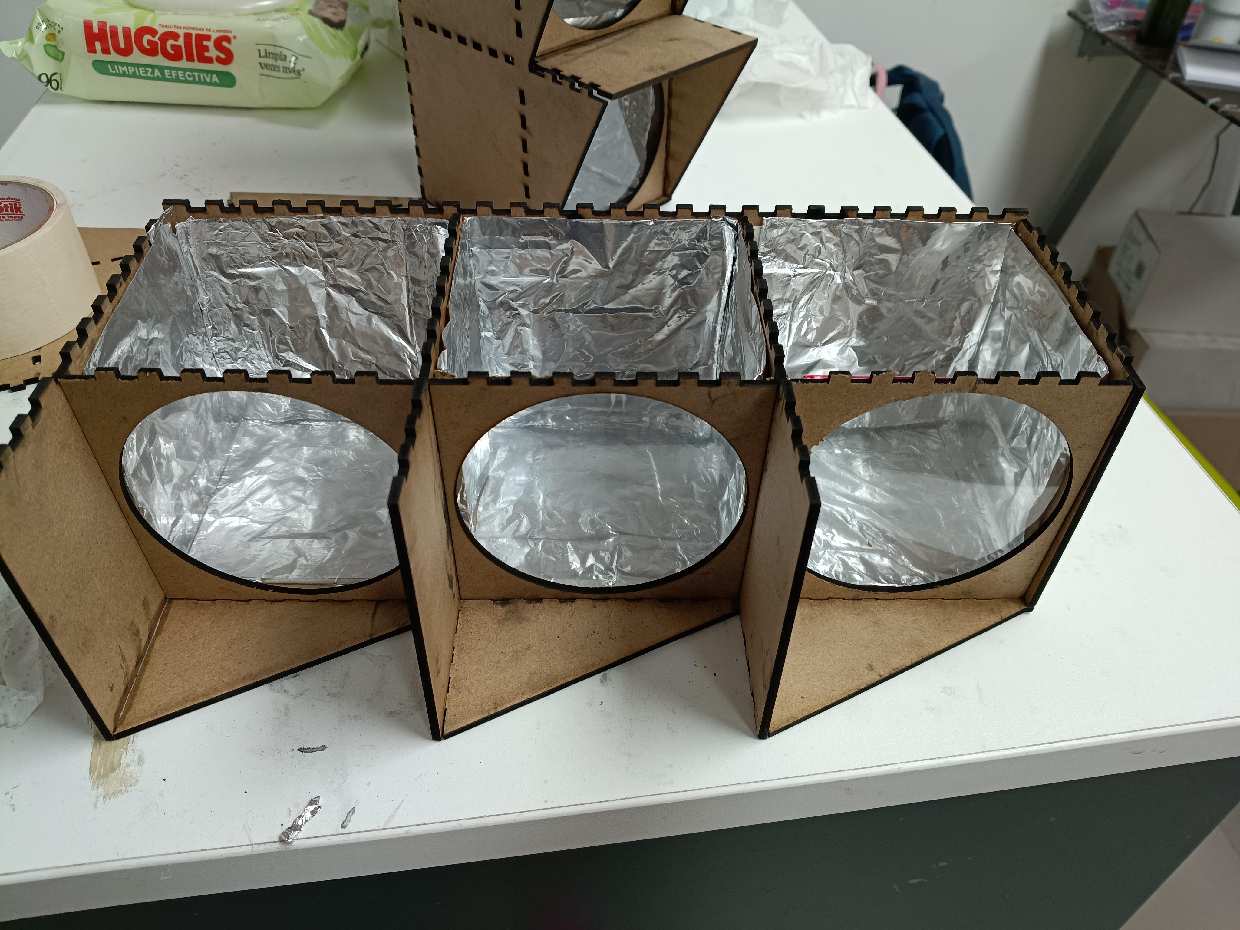
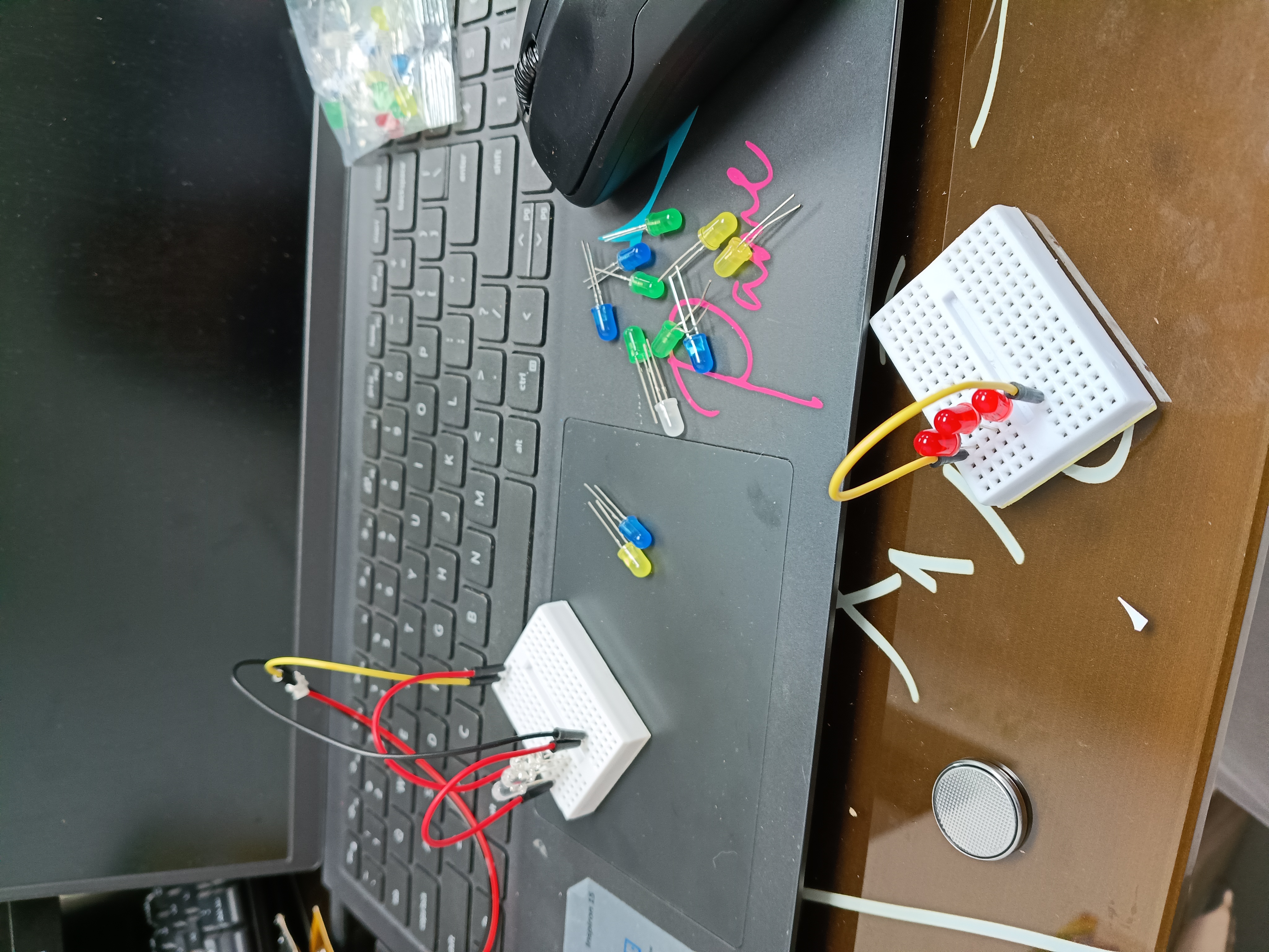
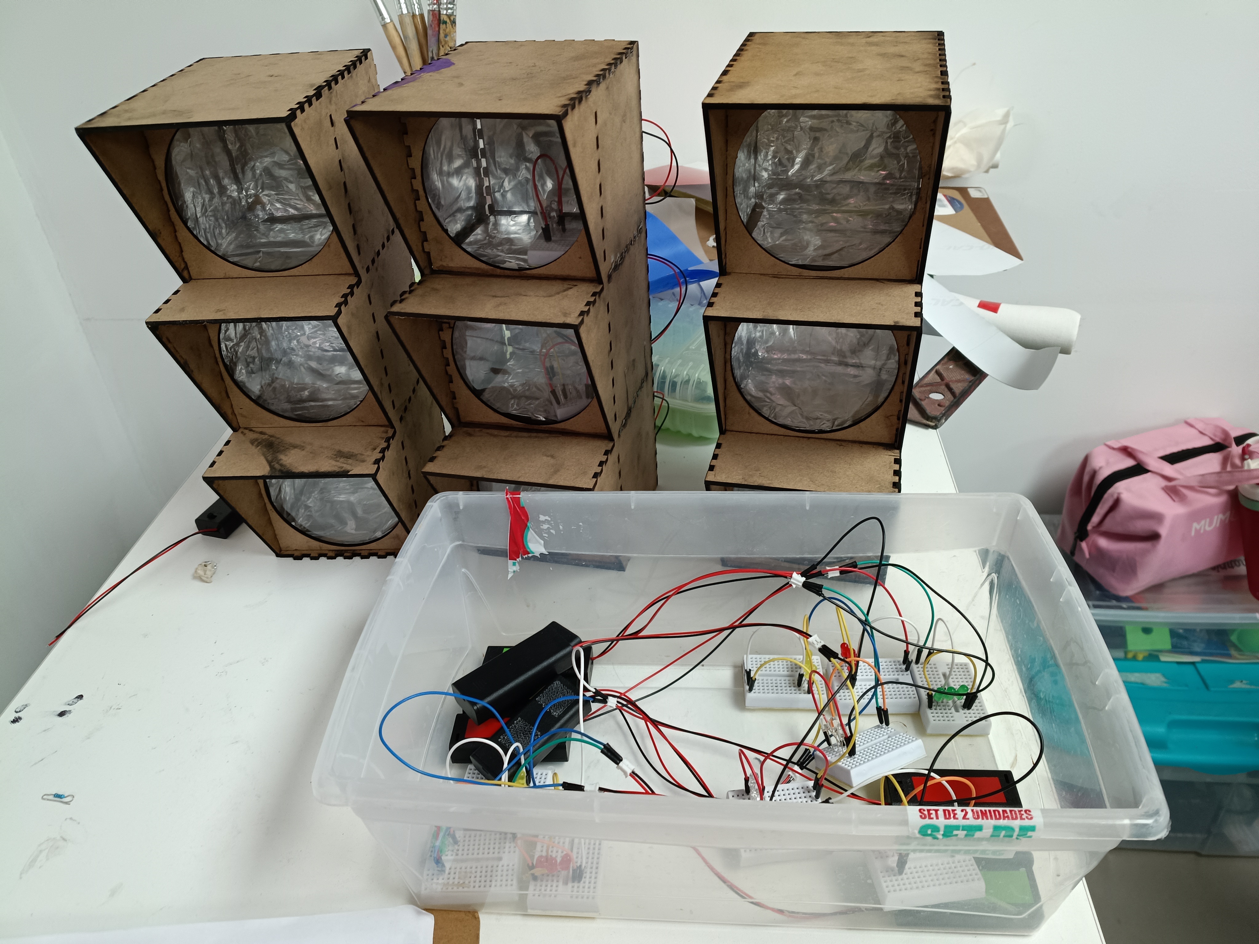
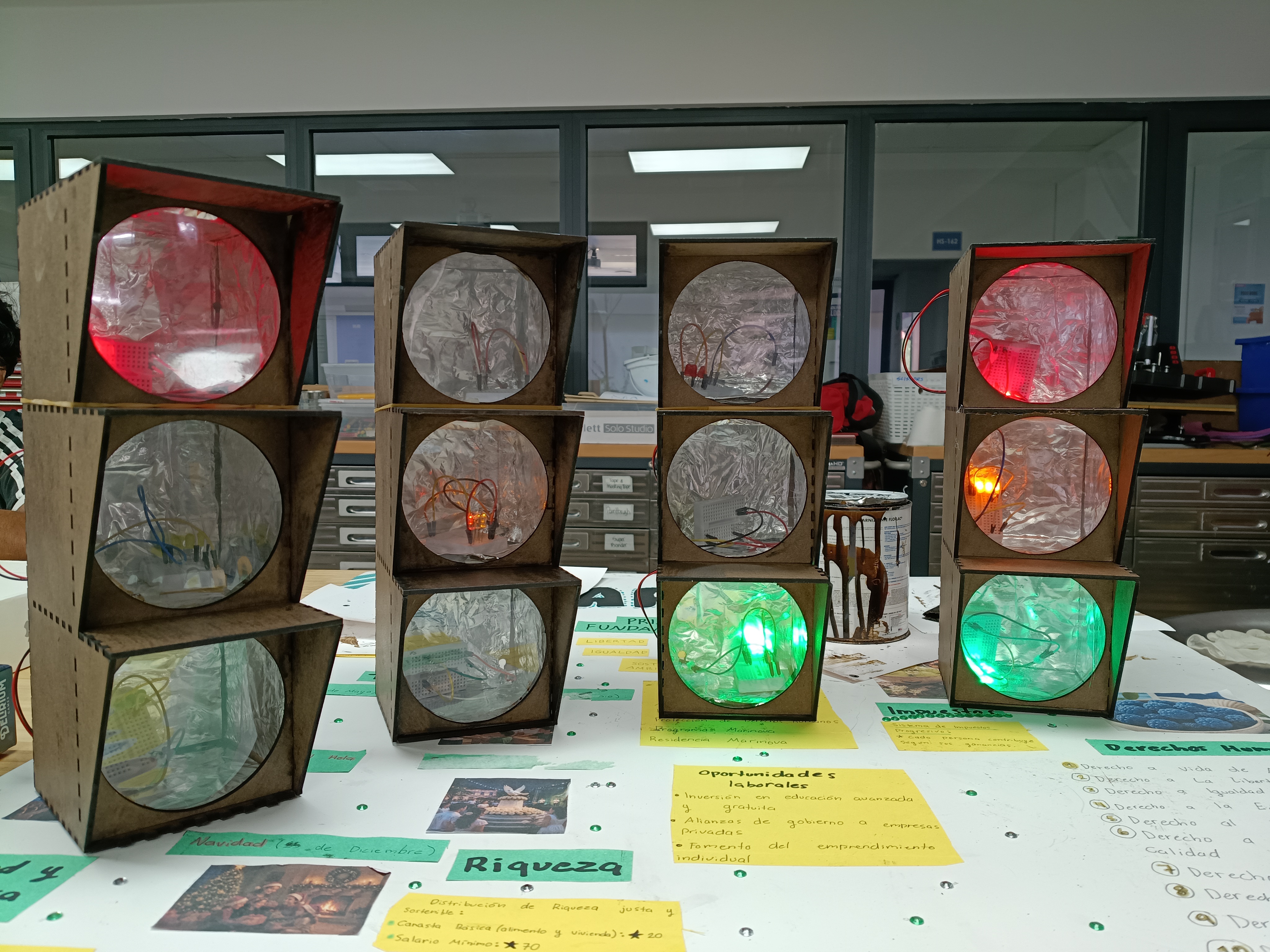
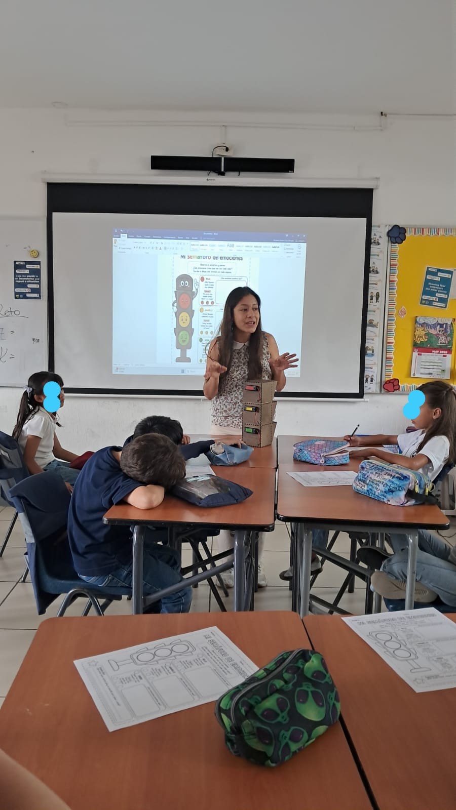
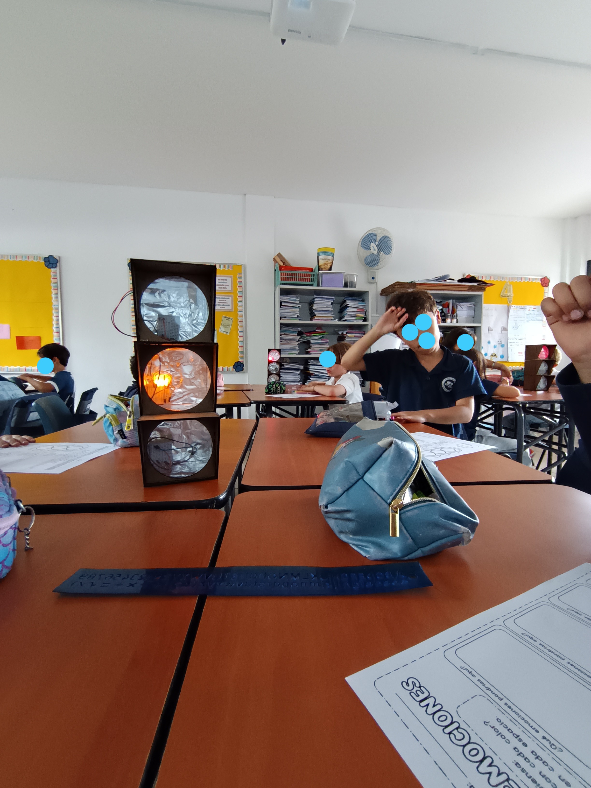
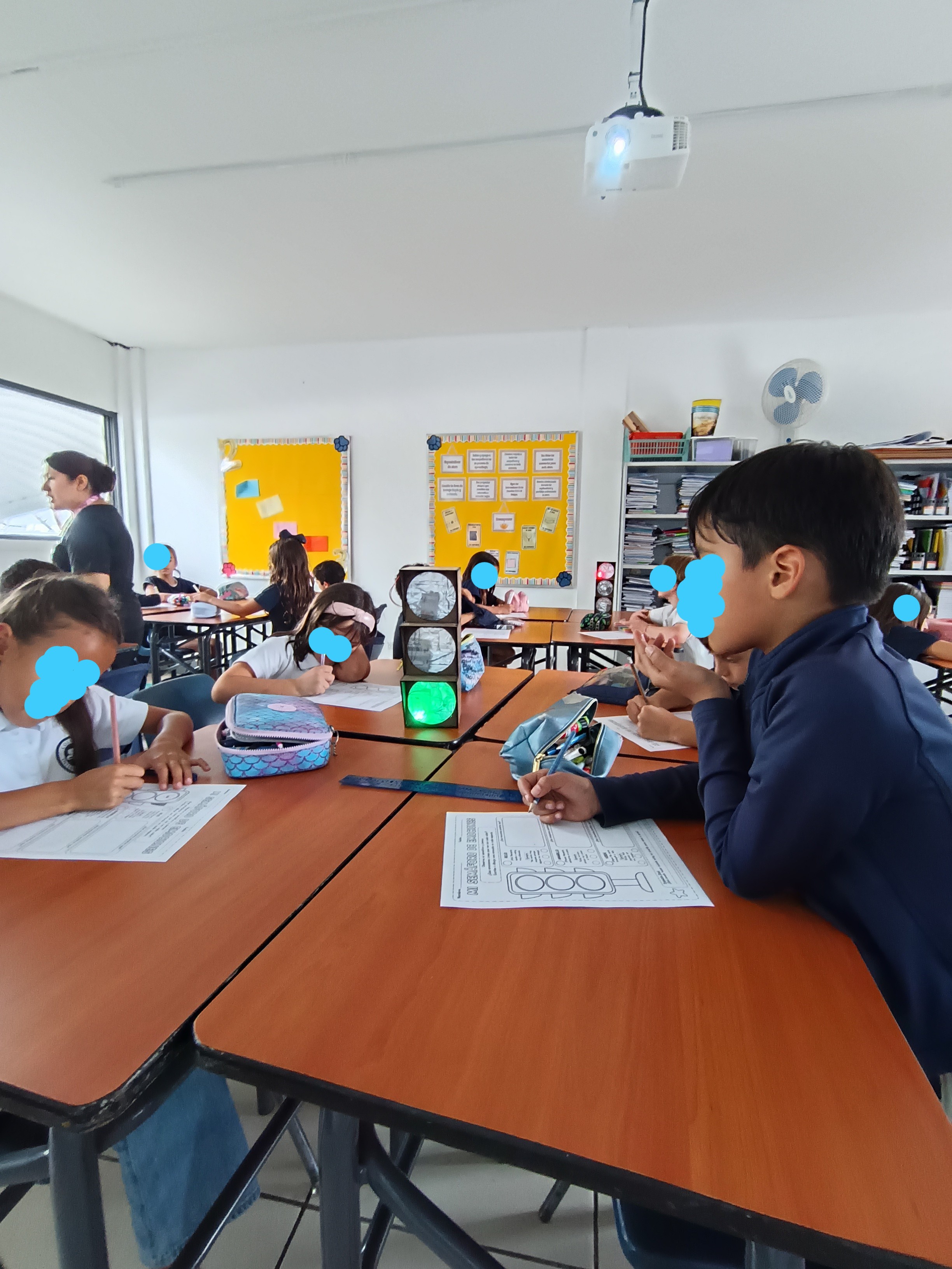
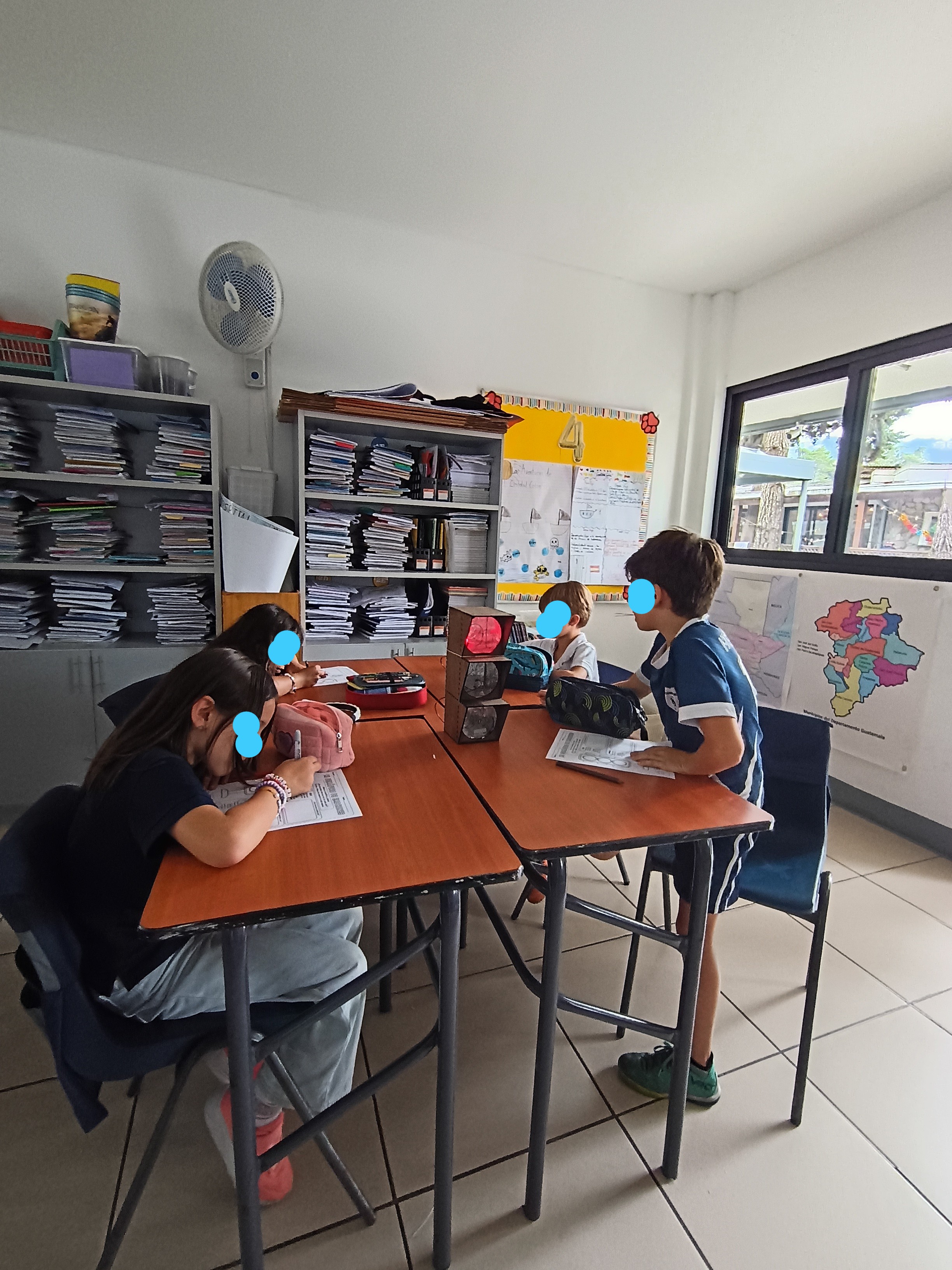
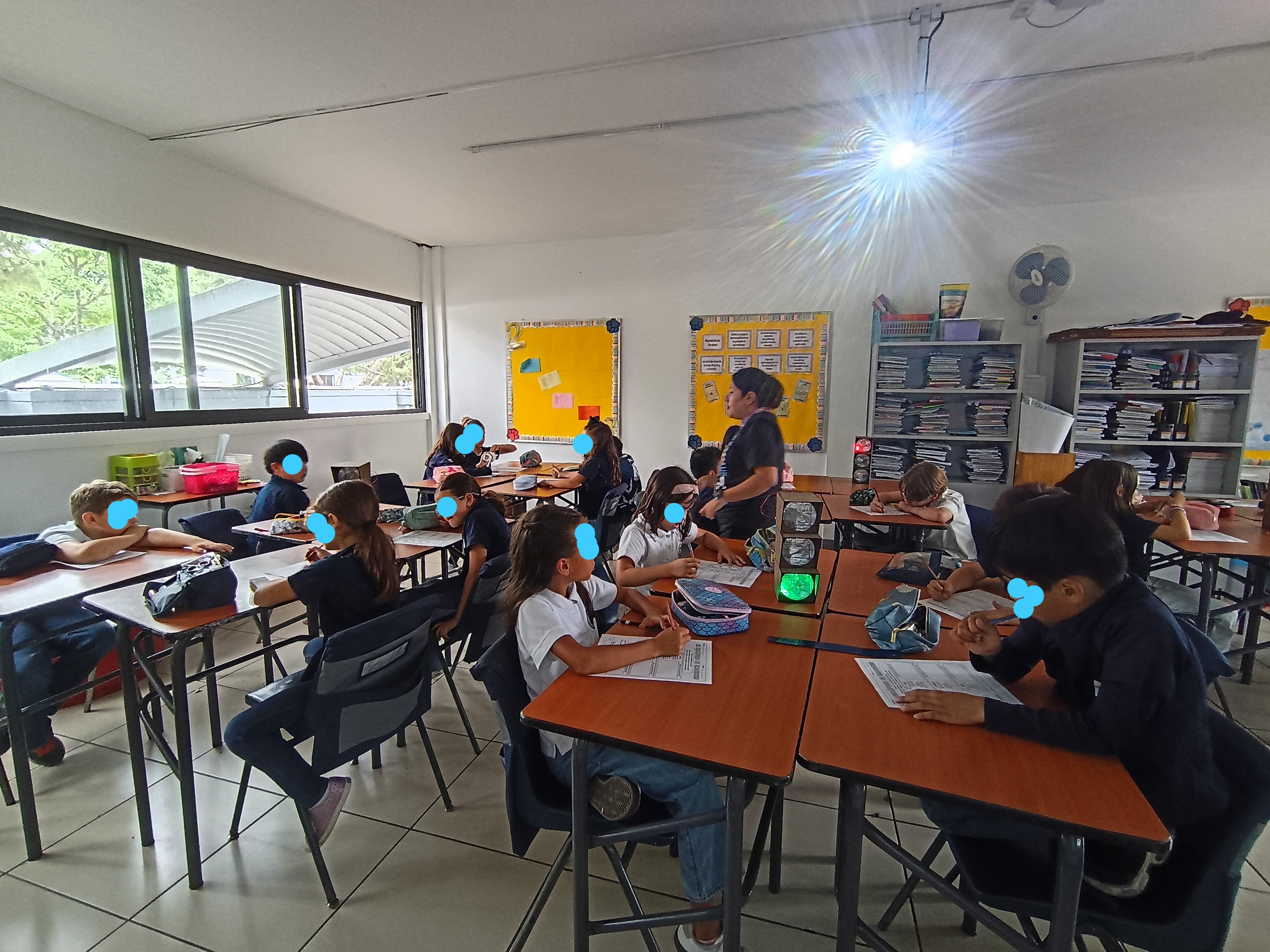
In this PBL project, both students and teachers noticed that time is often not used efficiently when addressing questions. The traffic light system they built helps improve this process. A yellow light indicates a minor question needing guidance, red shows the group is stuck and requires help, and green means they have resolved their doubts and are working confidently. This system promotes empathy among students and allows for better use of time during learning center activities.
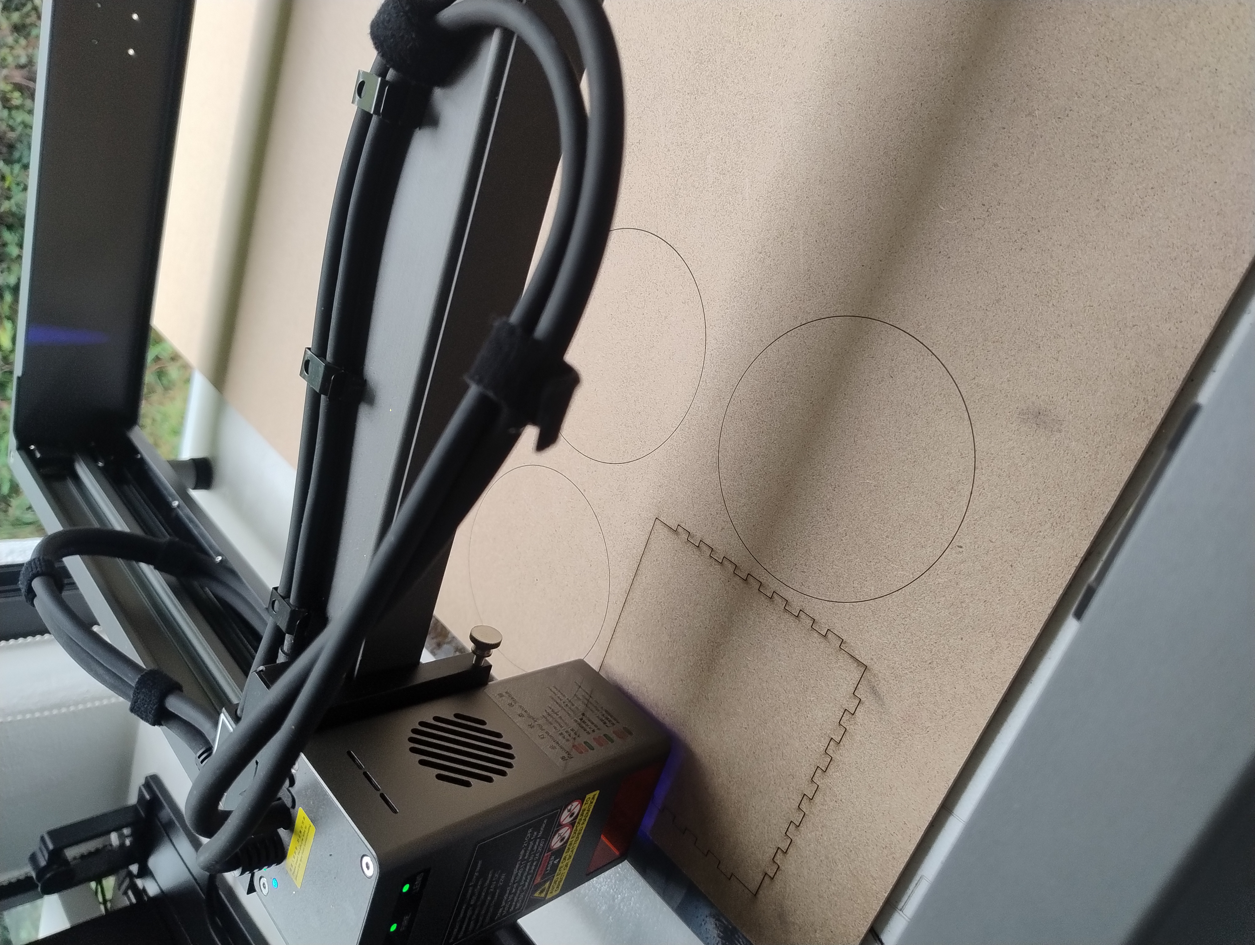
Note: Teachers felt very confortable with the introduction to the laser cutter, they faced some issues by installing the software because of the permissions in the school, but once they used my computer, they were able to choose a design to cut and engrave.
The timing was a big issue due we only have one laser cutter, so as a piece of advice, you can give the introduction to the laser cutter once they have the software installed and then they can find a spot in their free time to go to the FabLab and finish their design, so the rest won’t wait too much.
Estimated timing:
Laser cutter induction: 30 min.
Laser cutter use: 30 min.
Light system: 30 min.
Parts Assembly:20 min.
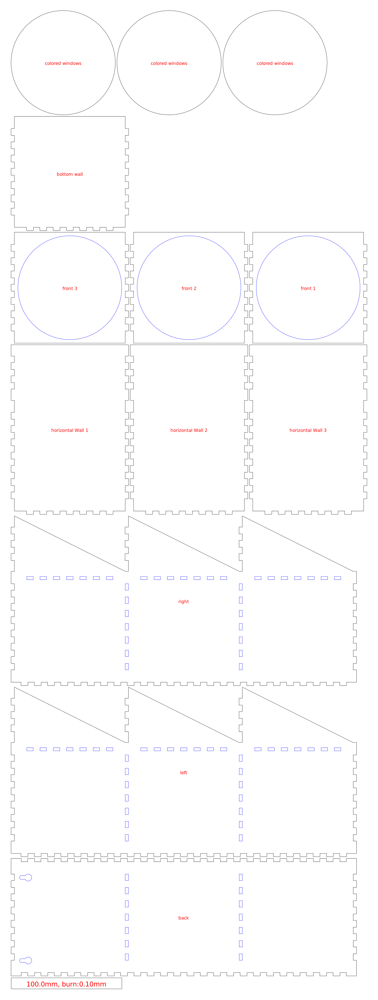
Students will receive the traffic light design and a step-by-step guide for using the laser cutter software. They will learn how to program the machine, select the appropriate material, and adjust the cutting precision to create the pieces for their traffic light. This process allows them to understand how to perform cuts safely and accurately using a laser cutter.
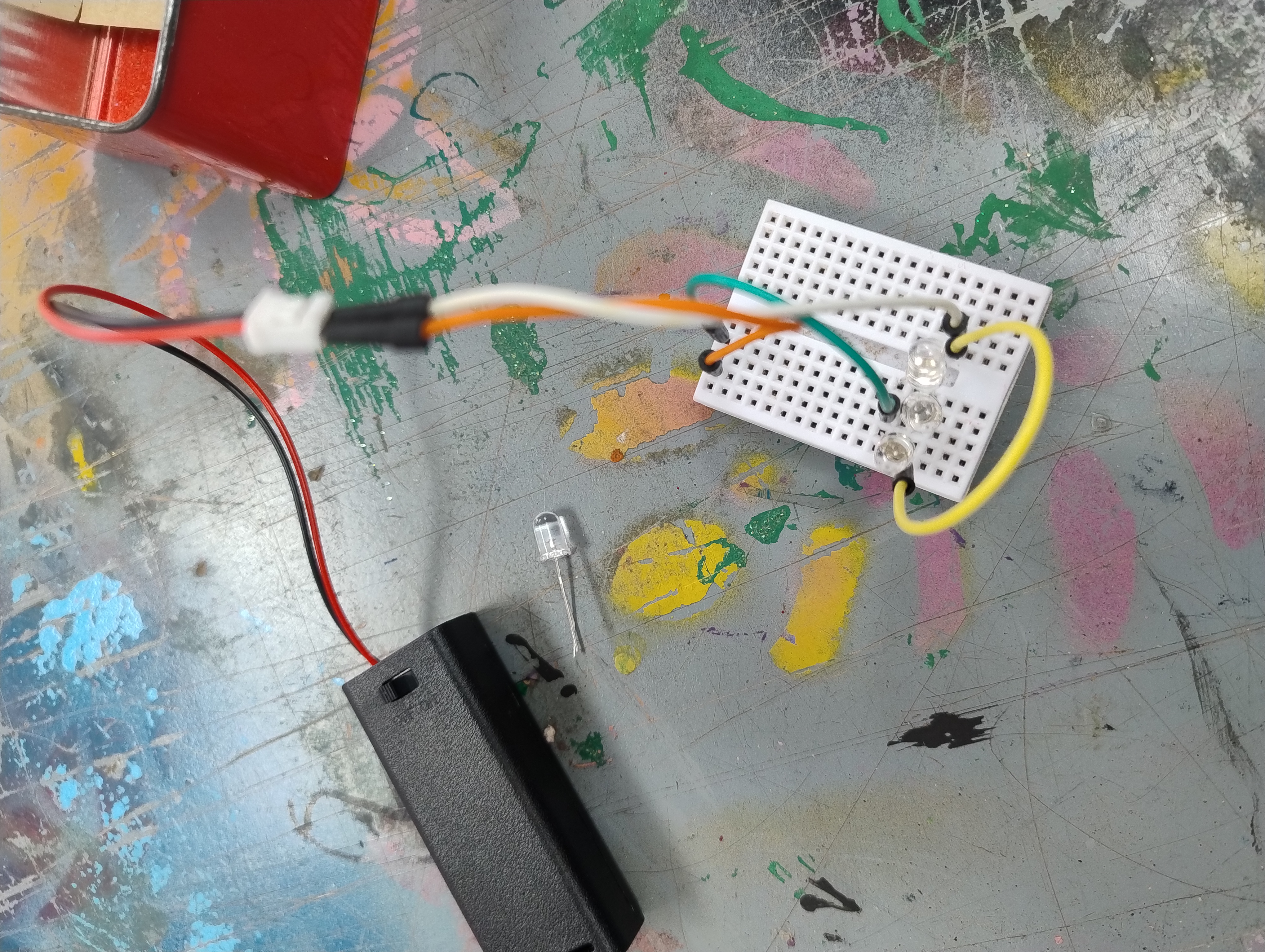
In this stage, we will build a circuit to add lights to their traffic light using led lights. They will follow a step-by-step guide to create their first circuit for the red light together as a group. Afterward, they will use the red light circuit as a model to build the circuits for the remaining two colors.
Students will assembly the traffic light pieces and the light system.
Having trouble? Let us know by completing the form below. We'll do our best to get your issues resolved quickly.
"*" indicates required fields