Vector Addition with Laser Cutting – SCOPES-DF

Lesson Details

Subjects *
Age Ranges *
Fab Tools *
Author

Author

Brady Snyder
Brady Snyder

Summary

  1. [PRE-CLASS] Cut pieces with laser cutter; vectors should be cut from 3.15mm Trotec MDF, while board can be assembled with either 3.15mm or 6.25mm Trotec MDF.
  2. Review 2D vectors with class using provided slides
  3. Introduce manipulative tool to class; demonstrate use and provide sample vectors to add (included in slides)
  4. Provide time (5-15 min) for students to discover appropriate methods for vector summation and to consider how subtraction might be performed.
  5. Return students to seats for explicit instruction of addition methods. Discussion encouraged, as students can share what they attempted and relate those methods to the instructed ones.
  6. Provide students with take-home worksheet (provided) covering vector representation, addition, and subtraction.


What You'll Need

  • All attached material
  • A laser cutter/engraver
  • Two 35cm x 31cm laser MDF boards (3.15mm or 6.25mm)
  • Wood glue or hot glue gun
  • Crafting tweezers or needle-nose pliers
  • An assembled vector grid board (multiple boards recommended for larger classes)

  • At least two vector arrows per board

Learning Objectives

The primary learning objective for this lesson is for students to be able to visualise how adding unit vectors at a variety of angles produces a final resultant vector, and then being able to find the magnitude and angle of that vector. This will be an essential skill throughout the Physics curriculum, particularly as we move into Dynamics and Free Body Diagrams.

Reflection

  • Could you have done this activity without the teaching aid you have fabricated? How do you think digital fabrication improves the activity vs utilizing traditional methods? What is the extra value?
  • While I could certainly have prepared for this activity with more traditional fabrication methods, digital fabrication through laser cutting provides several benefits over production by hand. One of the primary advantages is prototyping. This project required multiple prototyping stages to investigate the size and shape of the vectors, as well as looking at multiple methods of connecting the vector pieces together. Another major advantage is the speed of production and the ability to quickly assemble multiple kits with total accuracy to measurements. Additionally, laser engraving allows for the creation of a built-in grid and protractor on the base, which would otherwise have had to be carefully traced or printed on paper.


  • What are some challenges you expect when you do the activity with your class?
  • Design-wise, one concern I have is the structural integrity of the central peg. Material availability led to me using lower-quality MDF for the 3.15mm prints which could break with use. Pedagogically, my primary concern is initial buy-in, as many Grade 11 students like to pretend that they enjoy playing with toys quite a lot less than they really do. Additionally, I am certain that there may be unforeseen issues with the overall design that may contribute to inaccuracies in measurement. The physical materials will be supplemented by digital and visual representation, so I hope to give students multiple ways of visualising their assigned problems.


  • What did you learn during the fabrication process?
  • The primary lessons that I took from the fabrication process were learned in the early phases of initial ideation and design, and the later testing phases as well. By this point, I have a fair amount of experience doing vector design and using digital fabrication tools like the laser cutter, but I often struggle to find reasons to use them. Being forced to come up with an actionable lesson plan that uses digital fabrication made me take the time to not just sit down and think through what areas of my curriculum could use a constructed tool, but also to consult with Alec as a sounding board for those ideas and feedback. It was interesting to see the sounding board from the other side, as usually I am the one helping students to develop their own ideas in Design class or in our Grade 9 Science Fair. Additionally, after iterating through several versions of the vector connectors, I consulted fellow physics teachers and some of my students for feedback, which resulted in the final (well, current actually; there’s still plenty of updates I could make to improve the design) version.


The Instructions

Laser Cut and Assemble

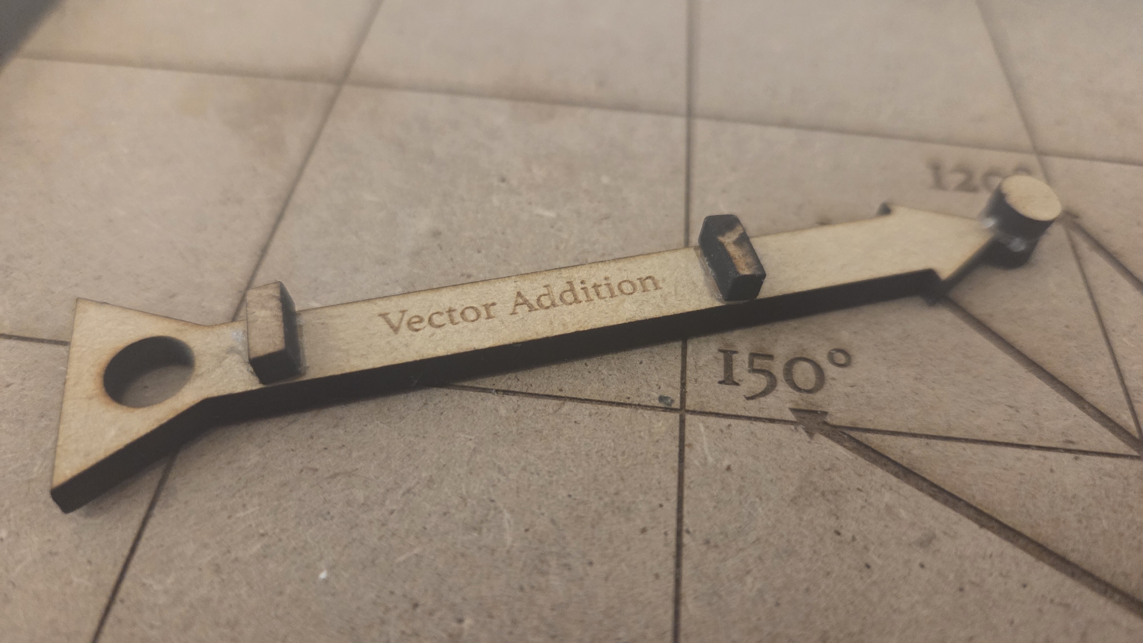
Using the attached .AI file, laser cut the board and vector pieces. All pieces can be cut together or separately, and each board should include at least two vectors. After cutting, some gluing is required to complete the peg connectors.

  1. Cut the vector pieces from 3.15mm MDF. Each piece should be accompanied by at least one cylindrical ‘peg,’ one round ‘hole,’ and two rectangular ‘feet.’ At least one additional peg should be cut as well, to be used later on the board. The peg is attached to the end of the vector arrow’s head, while the hole is located inside of the vector’s tail. The distance between the centre of the hole and the centre of the peg is considered to be 1 unit. The role of the peg is to connect to the hole of the following vector when using the triangle method of addition. Additionally, the hole can attach to the peg located at the origin of the board. The feet are required to stabilise the vector arrows, as they must be placed opposite one another when connected (face-side up vs. face-side down).
  2. Cut the board from sturdy MDF, either 3.15mm or 6.25mm. The board also includes a border frame both for aesthetics and to prevent pieces from falling off of the grid. The engraving for the grid may take some time, so proceed to step 3 while waiting for this to complete.
  3. Carefully glue the peg and feet to the indicated locations (the peg attaches to the large circle at the end of the vector’s head, and the feet attach to the rectangular engravings along the vector’s body) using hot glue or (ideally) wood glue. Tweezers or pliers may be required for this step, as these pieces are quite small.
  4. When the board is finished in the laser cutter, use wood glue to attach the frame around the edges of the grid, then glue an additional cylindrical peg to the centre of the unit circle. Allow all glue to set before moving any pieces.
  5. Connect one vector to the origin. This will be the starting vector.


Review Vectors

Spend some class time before the activity reviewing vector notation, vector components, and the distinction between magnitude and direction.

Go through the slides of Vector Review provided.

  1. Compare vectors to scalars. For each quantity provided, determine whether it is a scalar (directionless) or a vector (with direction).
  2. Trigonometric angle notation. For each of the three vectors, determine its absolute trigonometric angle from the positive x-axis.
  3. Vector components. Given the two provided vectors with magnitude and direction, determine the x and y-components using trigonometry.
  4. Vector notation. Review the six numerical representations of vectors (three with radial coordinates and three with Cartesian coordinates)


Activity

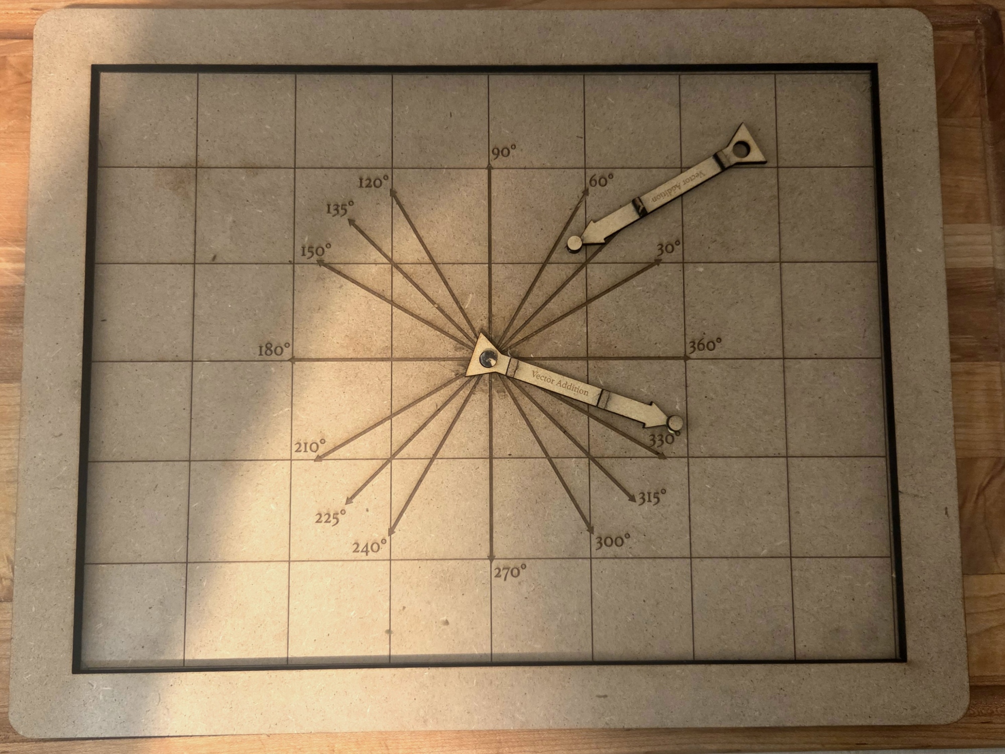
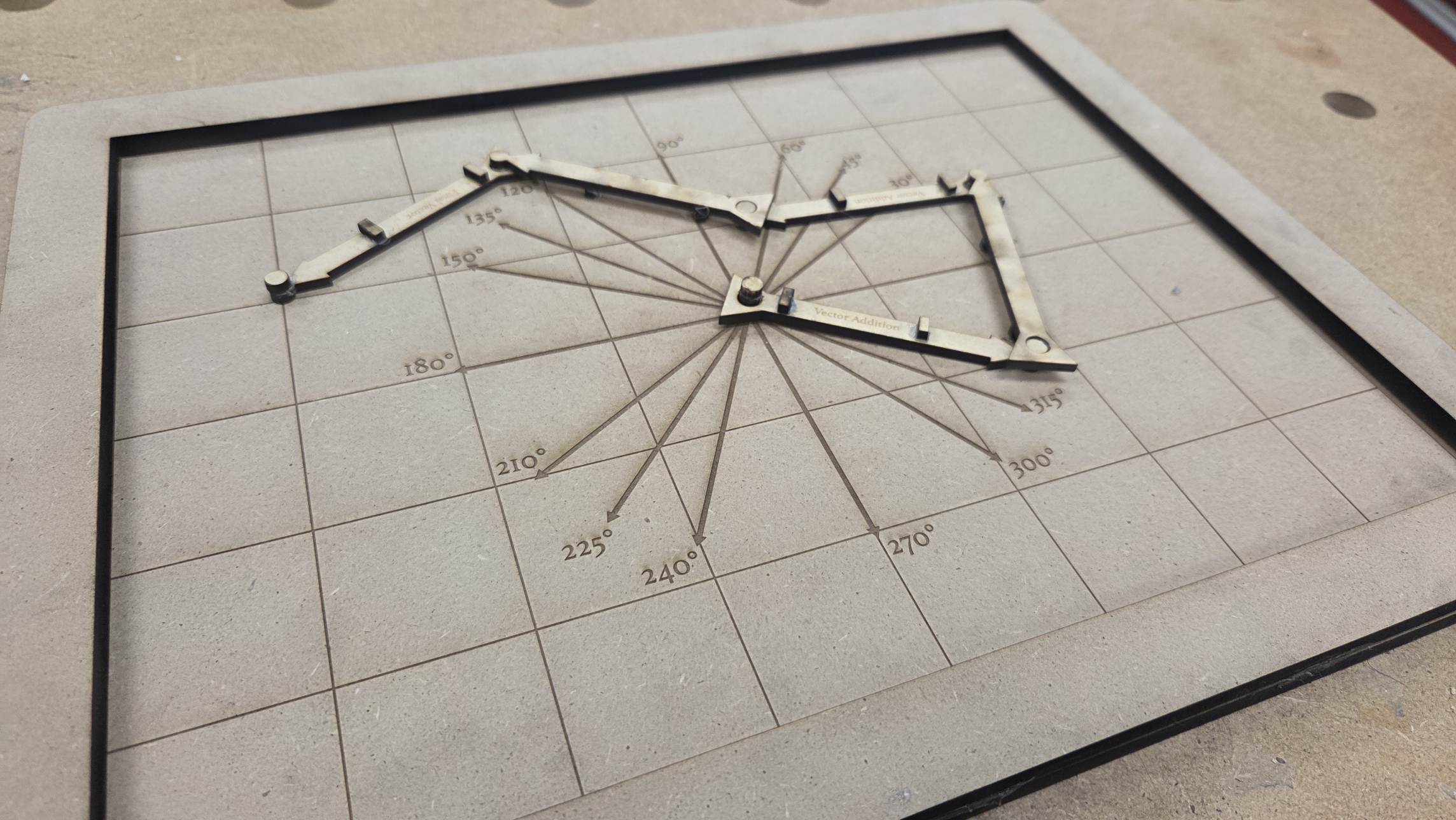
Introduce the board and vectors to students. Allow them time to play with different vector configurations to determine different ways that vectors can be added together.

  1. Show students the grid board and the vectors, and how they fit together with the peg-hole system.
  2. Give several vector angles and remind students about unit vectors (they always have magnitude equal to 1).
  3. Give students time to interact with the board and attempt to discover what a resultant vector is, as well as how its magnitude, angle, or components can be determined.
  4. Also provide students with the question of how subtraction might work.
  5. Timing is flexible, but should be no more than 15 minutes unless necessary.


Explicit Instruction

After the discovery activity, discuss what students attempted and go over proper methods for finding resultant vectors and opposite vectors.

  1. Return students to their seats.
  2. Allot at least 3-5 minutes of time to discussion of what students discovered: what worked? what didn’t? which elements of the vectors did they focus on to find the resultant – magnitude? angle? components?
  3. Introduce parallelogram method, in which added vectors are duplicated and the resultant is the diagonal of the resulting parallelogram.
  4. Introduce triangle method, in which added vectors are connected head to tail and the resultant is the third side of the resulting triangle.
  5. Introduce components method, in which the x and y components of the added vectors are summed and the resultant is assembled from those components.
  6. Introduce subtraction, in which subtracted vectors are replaced by their opposite vectors, equal in magnitude but opposite in direction.


Independent Work

Hand out the attached worksheet or similar, and give students the rest of the period to work individually on vector problems.Circulate to assist any misconceptions or difficulties.

Hand out the attached worksheet or similar, and give students the rest of the period to work individually on vector problems. Circulate to assist any misconceptions or difficulties.

Lesson Feedback

Contact us

Having trouble? Let us know by completing the form below. We'll do our best to get your issues resolved quickly.

"*" indicates required fields

This field is for validation purposes and should be left unchanged.
Name*
Email*
?