- Loading…
In the beginning, Samuel flipped a switch. And again, and again.
44 miles away, his assistant heard an eerie sound, and soon understood the words, “What hath God Wrought?”
Well, 1844 may not have been THE beginning, and that first telegraphic message may have been a little dramatic, but the importance of the moment involved the translation of text from a format that was already the most widely distributed in the world, to a whole new method of near instantaneous communication. But what WAS it?
The library of Congress documents the record of this message as a paper copy with raised dots and dashes, made to be translated later by an operator. How was it made? In this lesson, a simple circuit will show the simplest way to achieve a morse code messenger. Then, a modern touch adds a microcontroller to help with rapid translation.
https://www.morsewords.com/
https://www.loc.gov/item/mmorse000107
This lesson introduces students to concepts of abstraction through one of the oldest forms of electronic communication known, the Morse Code. Through an interactive primer, students gain experience with the precursor to binary logic, and practice a few basic circuitry skills as well.
In addition to those documented, this lesson also aligns with the following standards:
CSTA K-12 (2-CS-02): Design projects that combine hardware and software components
ISTE Student Standard 5c (Computational Thinker): Break problems into component parts, extract key information to develop descriptive models

This lesson builds a circuit with:
This lesson also depends on the following vocabulary terms:
Scaffolding and Differentiation:
This lesson explores over 180 years of technological progress and communication, and that can be a lot to take in. The steps as listed herein can be segmented further to support the varied ability of learners.
Students will build a circuit from physical parts or model one in TinkerCAD Circuits, which can be directly interacted with or programmed.
Students will investigate the abstraction at the heart of Morse code, and explain in their own words how it simplifies letters and numbers into pulses of light and sound.
Students will practice writing statements in Arduino C with variables, and conditionals.
Students will use their circuit and programmed model to communicate a message of their choosing, verifying that it does so effectively.
Students will communicate with a collaborative partner to encode and decode messages, and reflect on challenges with the model and medium.
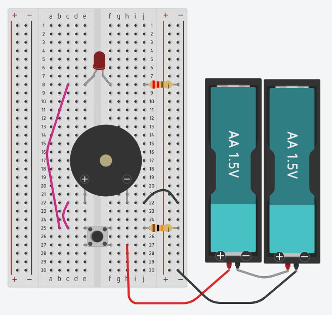
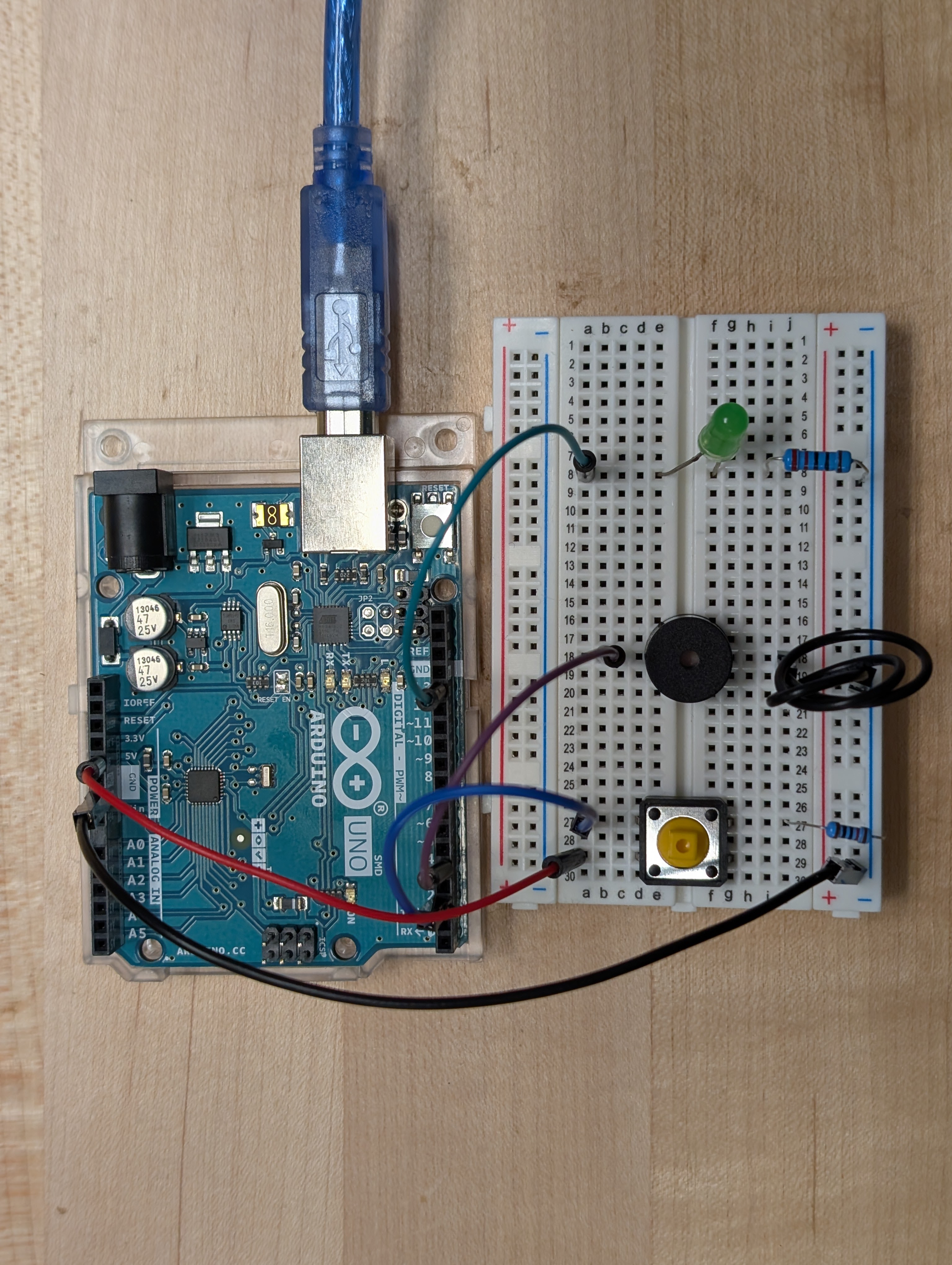
Add the LED, button, and buzzer to the breadboard. The spacing shown is intended to facilitate fingers still practicing the kind of nimble positioning a breadboard can command, with components spaced relatively far apart, so connections can be made without interfering with existing ones. TDD(Test Driven Development) statement #1: "When we connect the battery, Does the LED light up?" Make sure the resistor gets used with the LED. It might light up without it, but depending on the color of the LED, and the freshness of batteries used in the test, It might only light a few times then stop. TDD(Test Driven Development) statement #2: "When using the button, is the LED off when the button is not pressed, and on when the button is pressed?" Chunking: Whether modeling in TinkerCAD or building with real hardware, This step can be phased by focusing first on the light, with its resistor, connected to power without the button, then with the button to see how it changes the path. From there, swapping the light for the buzzer shows the similarities and differences between them, and then paves the way for exploring parallel circuitry.
Start with the breadboard, and use the LED to stand on opposite sides of what is called “the ravine.”
Add the button to the breadboard, also across the ravine, it appears to have 4 spots to which anything could be connected.
The power supply can be a battery, 2 AA’s in a holder is one format which could work.
If desired, the buzzer (piezo transducer) can be added to the board on a different row, with its positive terminal also on the left. A wire can connect its negative terminal to the ground row.
Included images show both configurations.
From here, each time the button is pushed, the light will illuminate and the speaker will buzz, if only faintly.
What other ways can we use electricity to send messages with only 2 options?
The early pioneers of the computer developed a new systematic approach to expressing the complexity of challenges with computing. Binary was a lot like morse, in that there were only 2 options… so why not just use the same method?
While we think of morse as being based on 2 options, called the dit and the dash, it actually turns out there was a third option. SPACE. Telegraph operators would pause between each pulse, a gap that distinguished between any two pulses in a letter, a different one between letters in a word, a longer one between words, and longer still between statements. This variety was also often inconsistent between operators, who were invariably human. Computers are capable of remarkable consistency, and this segment will use that consistency address the concept of abstraction as a means to translate human communication to the more simplistic dits and dashes. First as a part of making morse code out of letters numbers and punctuation that we understand, and converting them back again. Then, abstracting in a slightly different way to send any and all kinds of data in the ones and zeros of binary code. Binary gave rise to languages like BASIC, then FORTRAN, and COBAL and eventually JAVA and C, C++, and C#. This is by no means a hierarchical list of all languages, which all approach abstraction between the what needs to be encoded and the code that results.
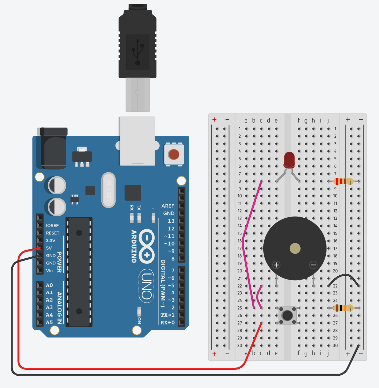
For this activity, it’s time to actually used the Arduino, and not just for power.
So, if the original circuit was built with a battery, its time to remove it.
Use wires to connect from the button input to the 5V port on the Arduino, and from the ground row to one of the GND ports on the Arduino.
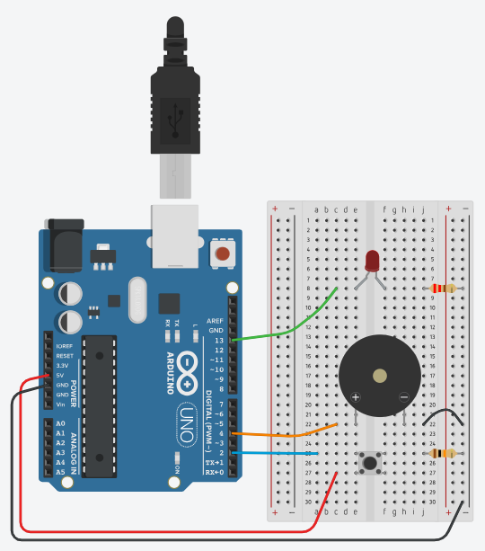
Next, adjust the wires connecting the LED and buzzer to the button. Now they should connect to ports 13 and 4 on the Arduino. One more wire is needed to connect the button to port 2.
Then we program.
Open an Arduino sketch, or a TinkerCAD Circuits document. TDD(Test Driven Development) statement #3: "After moving connections, Can Arduino instructions change the status of the LED?" TDD(Test Driven Development) statement #4: "Can the Arduino store instructions to ensure that each represented letter matches a specific pattern of dits and dashes."
The program opens with a set of variables, which serve to hold values to be used elsewhere in the program.
int dot = 76;
int dash = dot*3;
int pause = dash;
int wait = dot*7;
int speaker = 4;
int light = 13;
int button = 2;
Note how some of these don’t seem to have their own values, as much as they do some math to other values that already existed.
Next, one of Arduino’s two primitive functions, which must be included in order to run the program:
void setup() {
This function is called setup, so it seems reasonable that it should be used to specify things like whether the connected pins are serving as inputs or outputs.
 pinMode(light, OUTPUT);
 pinMode(speaker, OUTPUT);
 pinMode(button, INPUT);
Next, start the Serial Monitor so the code can be interacted with via text while it is running.
 Serial.begin(9600);
 while (!Serial) {
      ; // wait for serial port to connect. Needed for native USB port only
 }

 // send an intro:
 Serial.println("Send me text, and I will broadcast in Morse!");
 Serial.println();
Note here that “println” is not a mashup of “print in” or even “print 1 n” but of “print line” with a couple of missing vowels.
Time to close the setup function. Do so with:
}
The other primitive function in Arduino may also be included already:
void loop() {

}
Leave that one unchanged for now, it will be filled in after the next step.
At this stage, test to verify that the code will let the user open the Serial Monitor and send through a few characters, and prove that they are received.
Moving beyond the two basic functions, its now time to build a whole new function, to handle the most repetitive part of the program. TDD(Test Driven Development) statement #5: "Does the new function work for both lighting the LED, and buzzing the buzzer?" TDD(Test Driven Development) statement #6: "Do dot and dash values create pulses of noticeably different lengths?"
In the space AFTER the closing bracket of the loop() function, create a new function called “tap”
void tap( int toneLength) {
How many outputs and inputs does this function have? How can that be known?
This function needs to both turn on the LED and play a tone on the buzzer.
	digitalWrite(light, HIGH);
	tone(speaker, 3000, toneLength);
Here, the number in the middle of the tone statement sets the pitch of the note played.
Modify it to make it unique. (in case of learners with sensory sensitivities, this is a good one to suggest to bolster their agency about it.)
delay(toneLength);
Whether the tap is for a dit or a dash, the length will be passed to here, which will hold the light and sound for that amount of time.
	 digitalWrite(light, LOW);
	 delay(dot);
	}
Once the tap is done, turn the light off (the tone function sets its own ending), and pause for the length of one dit, the standard spacing between elements in morse. That’s the end of the custom function.
Test the code by adding function calls into the loop() function,
try things like:
tap(dot);
tap(dash);
It's now time to fill in the loop() function.
The first line uses an if statement to check whether any characters have been received by the Serial Monitor.
  // get any incoming bytes:
 if (Serial.available() > 0) {
  char thisChar = toupper(Serial.read());

   // say what was sent:
   Serial.print("Broadcasting: ");
   Serial.println(thisChar);

}
Note that the phrase “Serial.available() > 0” is inside parenthesis, like inputs and it is followed by a { , like a function. Inside a new type of variable, this one a “char,” which stores the character which is read from the serial monitor, converting it to uppercase. What happens if no characters are available?
With conditional statements, if the condition is not met, the statement inside it does not execute.
 else {
  // read the state of the pushbutton
  int buttonState = digitalRead(button);
   // check if pushbutton is pressed.
   // if it is, the button state is HIGH
   if (buttonState == HIGH) {
     digitalWrite(light, HIGH);
     tone(speaker, 3000, dot);
   } else {
     digitalWrite(light, LOW);
   }
   delay(10); // Delay a little bit to improve performance
 }
This will execute if there is no input from the serial monitor, and would allow the user to push the button for a manual mode.
In order to complete the translator, a conditional statement is needed which has more than two options.
Add a new line after “Serial.println(thisChar);”
Begin the new statement like so:
 switch (thisChar) {
           case 'A': tap(dot); tap(dash); delay(pause); break;
           case 'B': tap(dash); tap(dash); tap(dash); tap(dot); delay(pause); break;
           case 'C': tap(dash); tap(dot); tap(dash); tap(dot); delay(pause); break;
           case 'D': tap(dash); tap(dot); tap(dot); delay(pause); break;
           case 'E': tap(dot); delay(pause); break;
           default:  delay(wait); break;
           }
In this statement, the letter stored in “thisChar” is compared against each case in the switch.
If a match is found, the statements after it execute until the “break;”
Of course, in order to find matches for letters after “E,” more “case” statements will be needed.
This is probably the easiest place for students with high confidence to race ahead on setting up all the case statements for the rest of the alphabet, or even numbers and symbols.
Once enough case statements have been added, upload the code and open the Serial monitor to input phrases to be translated, then watch and listen to the message as displayed in morse taps.
Then, pair up with someone else who has a working prototype, and practice sending and receiving messages between each other. What challenges are encountered? Reflect and pose solutions.
A revised sketch is included in the attachments with allows two boards to send and receive messages encoding and decoding alike.
the LED port of one board can be routed with a wire to the Button port of another.
At minimum, a wire should also span between the ground ports of the boards to ensure common ground.
With a third wire running the opposite path between LED and Button, each board is capable of sending morse that is either tapped out on the button, or typed into the Serial monitor, to be received on the other board and displayed in light, buzzer, and serial monitor as well.
This solved the problem of no support for receiver, and only requires teaching about millis() and the unsigned long data type.
Having trouble? Let us know by completing the form below. We'll do our best to get your issues resolved quickly.
"*" indicates required fields