
- Loading…

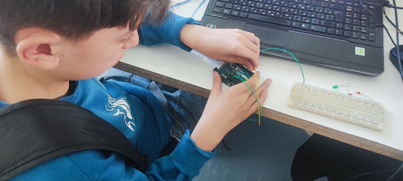
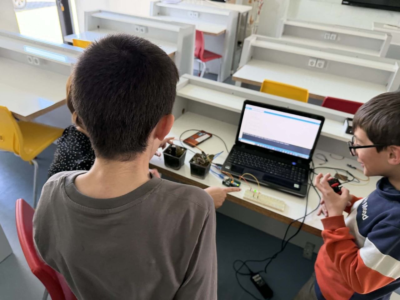
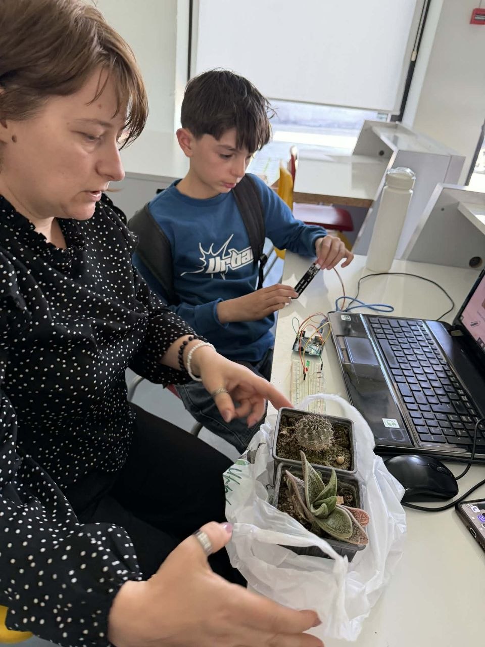
During the lesson, students learn the basics of physical programming, biology and geology.
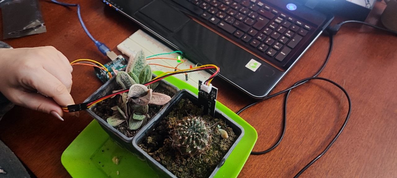
The objective: create a simple system that will inform us about the condition of the soil in houseplants.
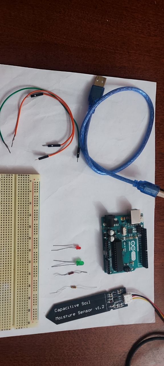
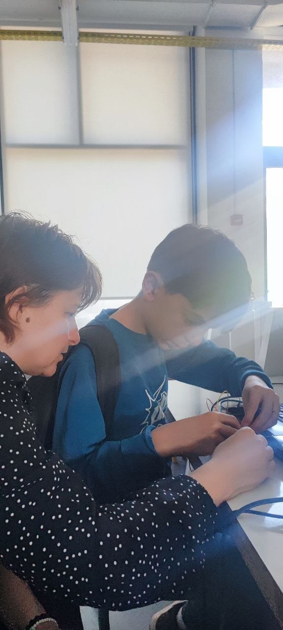
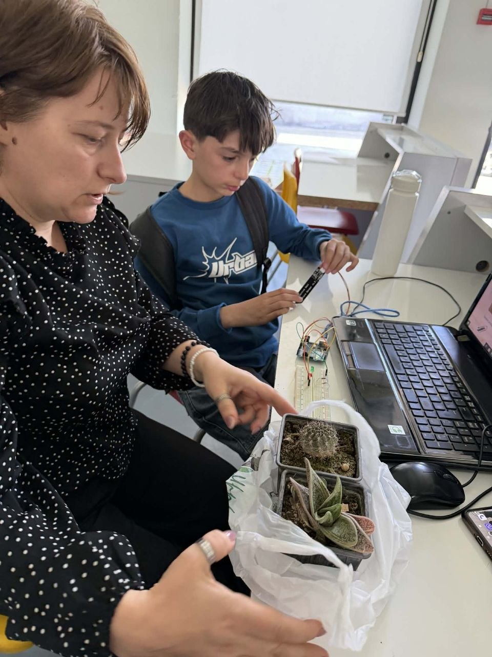
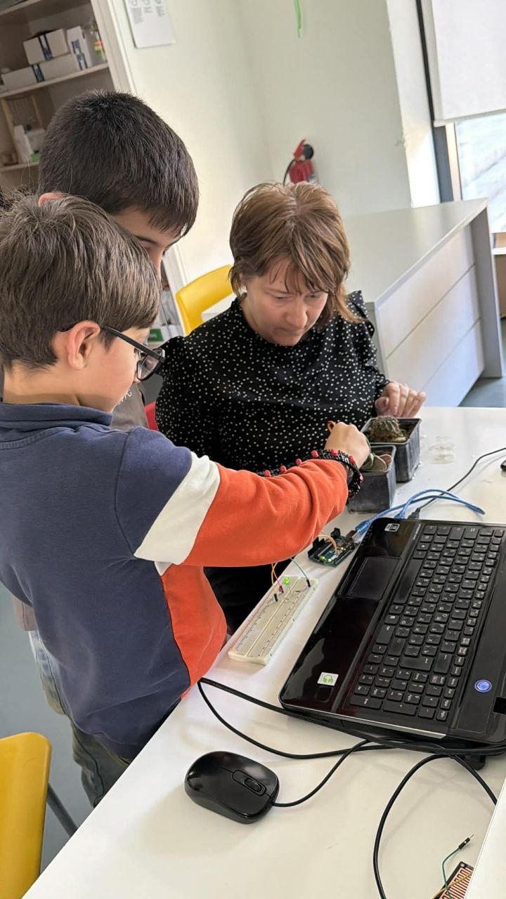
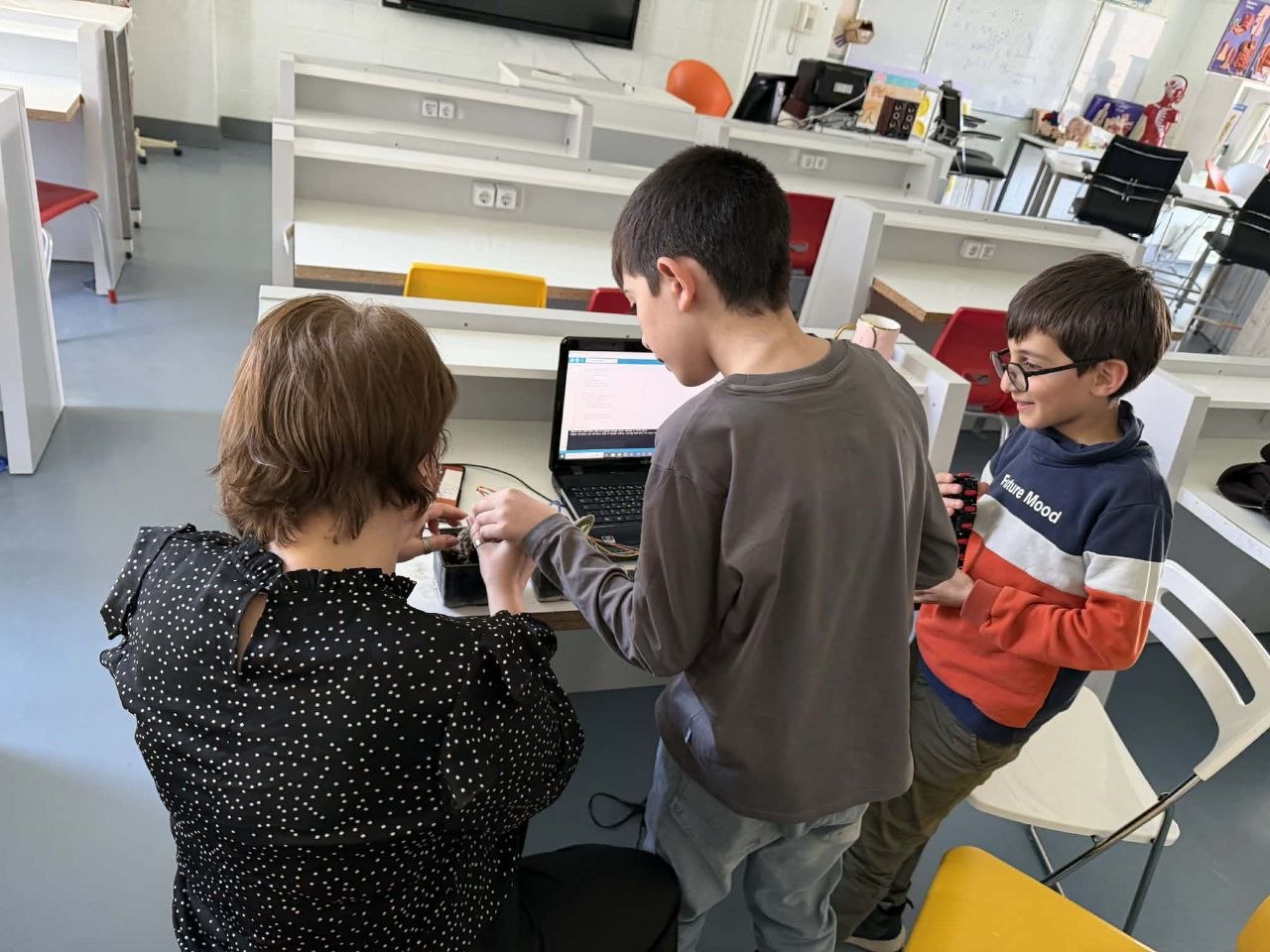
Hardware:
Software:
Learning objectives:
Assesment protocol for this lesson
Some of the concepts were challenging for students of this age. Despite this, the lesson successfully transitioned students from passive data reading to active system design. By removing the screen and relying on two LEDs, students were forced to determine “healthy soil” logically, rather than simply by reading a number. The most important takeaway was the students’ understanding that human-defined context (calibration) is essential for sensors to operate effectively.
This lesson could be expanded or improved upon to create an alert system for houseplants, adding a bell and/or a touchscreen to display soil dryness readings.
This section of the lesson discusses the problem of plant needs. Students are also given the opportunity to propose a solution to the alerting problem.
The lesson begins with a discussion of the basic needs of plants.
Then the students play a scratch game created by teacher-collaborator Suzannа Martirosyan.
Link to the game here
After discussing the teacher asks questions:
“What do plants need to grow?”
How do you know if a plant needs water?
Do different plants need the same amount of water?
How can a plant’s soil tell us it needs water?
Before putting the sensor in a plant, students need to see how different earth materials hold water. and determine exactly when their plant is "thirsty." After that students test how the environment "steals" water from the plant’s leaves.
The Setup: Take two cups—one filled with sand and one with potting soil.
The Action: Pour the same amount of water into both and insert the sensor.
The Observation: Watch the numbers on the screen. Does the sand “dry out” faster than the soil?
The Concept: This teaches soil-water relationships. Students learn that “moisture” depends on the texture and space between soil particles.
The Action: Stop watering a test plant for a few days.
The Observation: Watch the plant closely. The moment the leaves start to droop or feel soft, look at the sensor reading.
The Goal: That specific number is the Permanent Wilting Point.
Students test how the environment “steals” water from the plant’s leaves.
The Setup: Group A puts their plant in the shade. Group B puts theirs in front of a fan or under a bright lamp.
The Action: Time how long it takes for the moisture levels to drop.
The Concept: Students will see that the plant in the “wind” or “sun” loses water much faster. This explains transpiration—how plants “breathe” out water vapor, especially when it’s hot or windy.
Objective: Discussion on basic Arduino knowledge.
Discussing and introducing questions:
What is Arduino? Explain that it is the “brain” of the project. Like a human brain receives signals from the skin (touch) and tells the hand to move, Arduino receives signals from sensors and tells LEDs to light up.
Input vs. Output: * Inputs: Sensors (Soil moisture, buttons, light sensor
Outputs: Actuators (LEDs, buzzers, motors).
The Software: Introduce the Arduino IDE. Explain that we use “sketches” (code) to tell the brain what to do.
Key Terminology:
Digital: Only two states—ON (High) or OFF (Low).
Analog: A range of values (e.g., 0 to 1023) used for measuring “how much” moisture is in the soil.
Objective: Building and programming a single LED circuit. The Task: Connect a single LED to Pin 13 and Ground (GND
Safety First: Explain why we use resistors (to prevent the LED from “blowing up” from too much current).
Polarity: Teach students that LEDs have a long leg (Positive/Anode) and a short leg (Negative/Cathode).
The Code: Introduce the Blink sketch.
void setup() {
pinMode(13, OUTPUT);
}
void loop() {
digitalWrite(13, HIGH); // Turn LED on
delay(1000); // Wait 1 second
digitalWrite(13, LOW); // Turn LED off
delay(1000);
}
Activity: Students must successfully make their LED blink before moving to the main project.
Constructing the Plant Saver full system.
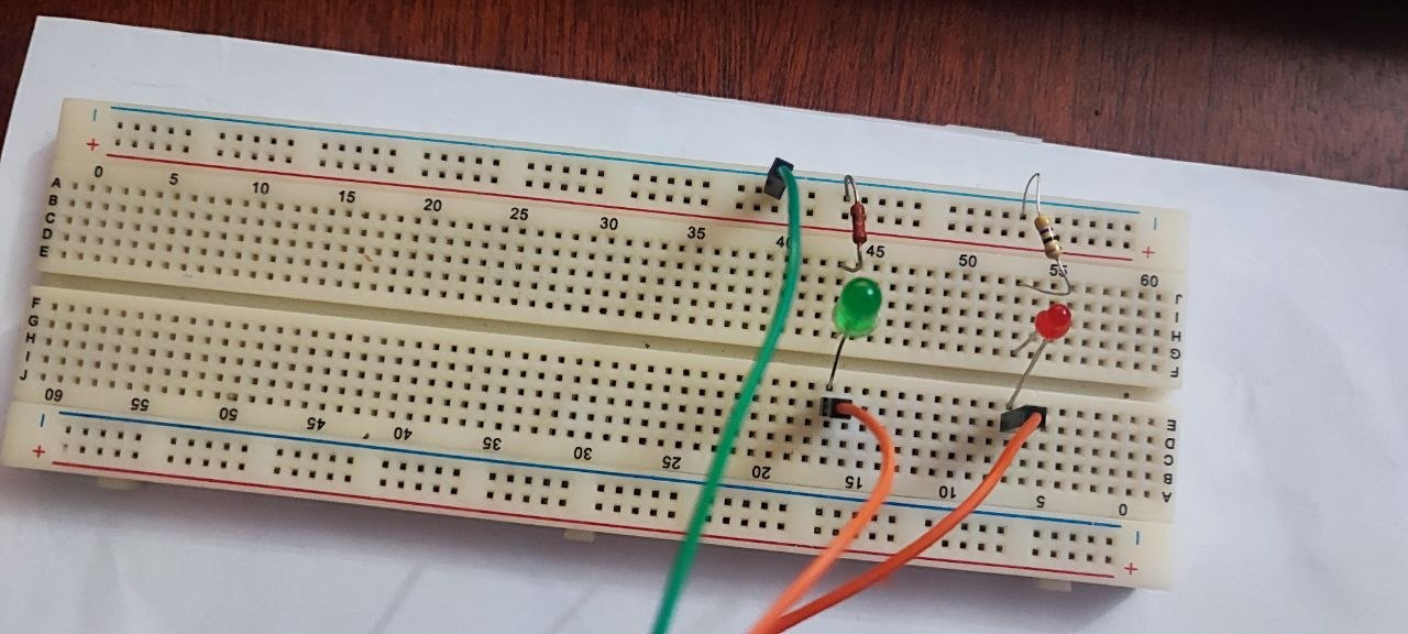
1. The Hardware Setup
Students will now expand their circuit to include:
2. The Logic (Programming)
Explain the if/else logic: If the soil is dry, then turn on the Red LED. Otherwise, turn on the Green LED.
const int sensorPin = A0;
const int redLED = 3;
const int greenLED = 2;
void setup() {
Serial.begin(9600);
pinMode(redLED, OUTPUT);
pinMode(greenLED, OUTPUT);
}
void loop() {
int sensorVal = analogRead(A0);
Serial.println(sensorVal);
if( sensorVal > 450) {
digitalWrite(redLED, HIGH);
digitalWrite(greenLED, LOW);
}
else{
digitalWrite(redLED, LOW);
digitalWrite(greenLED, HIGH);
}
}
Having trouble? Let us know by completing the form below. We'll do our best to get your issues resolved quickly.
"*" indicates required fields