- Loading…

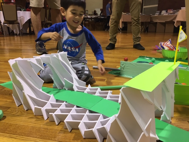
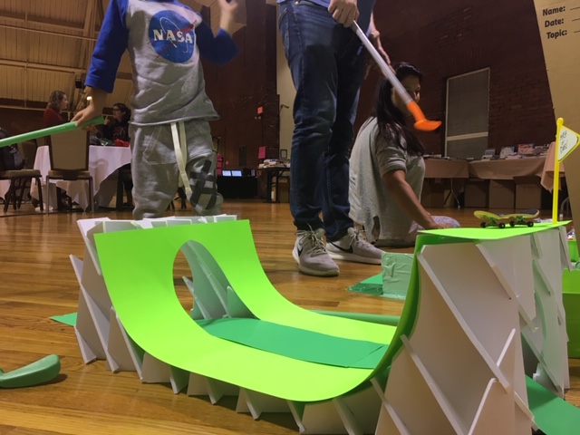
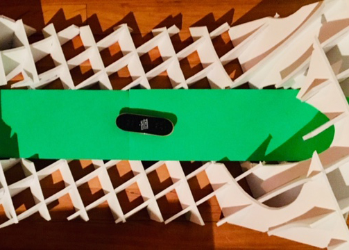
In this lesson you’ll learn how to make complex and precise geometric assemblies – like the skateboard halfpipe seen here – without the need for a laser cutter. Inherent to this lesson is the development of an understanding of projective geometry. Particularly, this covers concepts such as geometric workplanes, scale, perpendicular and parallel, and tolerance. In addition, this lesson develops fine motor skills and patience.
This lesson was originally built as a 3 day hands-on project during the 2019 Constructing Modern Knowledge conference in NH, USA.
Here’s a link to collaborate on the original TinkerCAD Skatepark!
SAFETY FIRST! This lesson requires using precision cutting blades – such as an X-Acto Knife or similar box cutter – which are very sharp. Children should be supervised at all times while using such tools.
Use your favorite 3D modeling program - I like TinkerCAD because it's web-based and free - to create a solid 3D model of the object you'd like to make. I've created a whole skatepark in TinkerCAD simply by adding and subtracting geometric primitives together such as rectangular and triangular prisms and ellipsoids, Students can explore concepts of scale, transformation, and work-planes and world-planes using basic commands in the program. TinkerCAD is also an online community, so it is a nice way to introduce students to online profiles, file-sharing, and cloud-based computing.

TinkerCAD can export .stl file types (good for 3D printing too), which means you can take your digital work with you into different programs. In digital fabrication practices this importing/exporting - the transporting of files from one program to another - is often referred to as a 'workflow'. Now, export your geometry from TinkerCAD and import it into the program called Fusion Slicer. This program will automatically generate laser-cutter ready files (2D files) from your 3D geometry. It does this by projecting slices - or planes - through your model. These slices can be parallel to each other, perpendicular to each other, or even radially distributed in 3D space! The program then generates laser cutter cut sheets (vector files) with the individual parts laid flat, nested - or arranged compactly - and also labeled for easy assembly. Explore all the parameters on the left hand side of the interface to adjust the slices for your particular model.

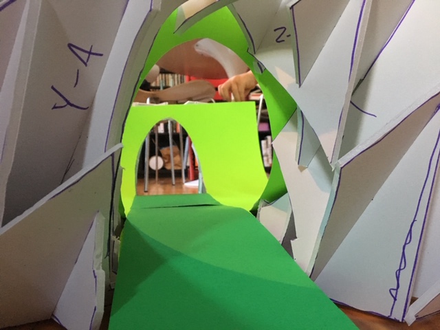
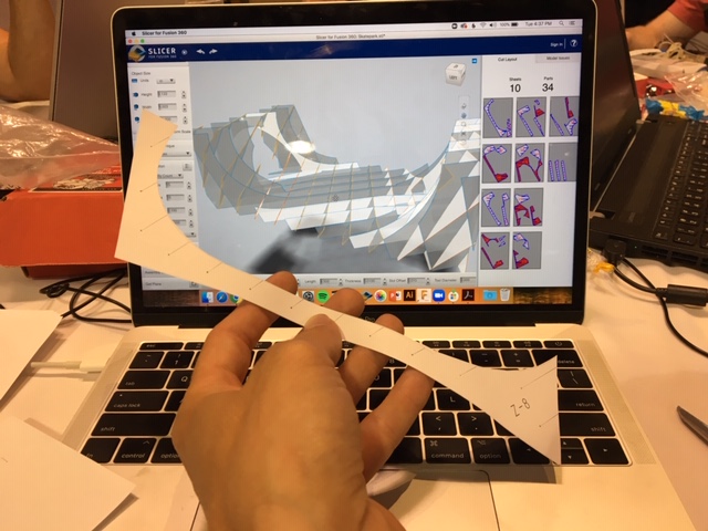
Pictured to the right is a 'cut sheet' generated in Fusion Slicer. for my halfpipe design You'll notice a few things about this cut sheet: first, there are red parts and grey parts. The red parts indicate that some error has occurred in the slicing process and some rework may be needed on your part. Often the error is simply that some parts are too small or that there's a geometric collision which may make assembly difficult. It's recommended that when you see red parts, you should go back and modify your slicing parameters: perhaps change the number of slices, or the angle of projection, or the some other factor. Second, you'll notice each part has numbers and letters. These indicate which plane the slices are in - X, Y, Z planes (or more) and also, which slot from one part interlocks with a slot from another part. Lastly, you'll notice that while the parts are 2D on the screen, in reality the material in which you cut these parts does have a dimension. Cardboard often is ~1/8" thick, for example. You're material thickness should be represented by the thickness of the slots in each of the parts. Be sure to accurately measure your material thickness when generating your slicer parameters.

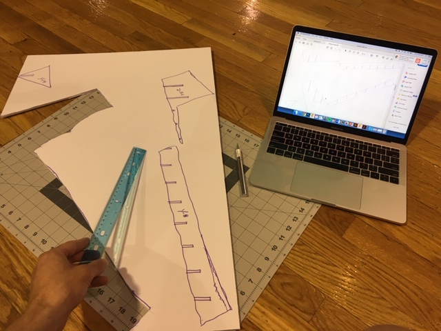
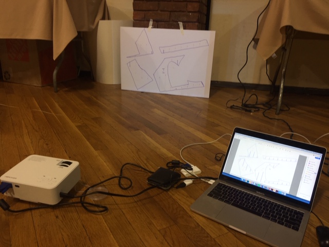
Here's the 'unplugged' part of this lesson! Instead of sending your cut files to a laser cutter, send your files to a digital projector. Project each cut file onto your material and trace them by hand. One challenge in doing this is setting up the projector so that the image it projects is perpendicular to the material. One could imagine a really skewed image if the projector was at an angle. This would result in inaccurate parts. Another consideration is the distance that the project sits from the material. If the distance is too great, the parts would be too large; if the distance too close, the parts would be too small. The question becomes: at what distance away from the material should the project sit? Lastly, one must overcome the challenge of accurately tracing all the parts. Easier said than done, but here is where the issue of tolerance comes into play. For many applications the laser cutter is overly precise. You'll find that depending on the size of your object, the errors of hand tracing become negligible. An alternative to the projector would be using a large format printer. If you have a printer you can print the parts, then overlay the printed sheets on rigid stock material such as foam-core or cardboard.

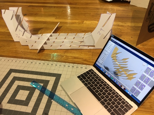
This part is difficult and will take time. It is also dangerous, so please take every precaution if students are working with the cutting knifes. I cut my parts out of white foam-core board but cardboard could also be used. It's also critical to keep the blades very sharp if they're to be effective cutting tools. Therefore, it is critical to use a cutting mat and to frequently replace the blade. It's also helpful where possible to use a cutting edge, such as a metal ruler or yardstick. When you're ready to assemble, be sure to use the Assembly Steps feature in Fusion Slicer. It creates an assembly animation - like an IKEA guide - which is helpful for seeing which part goes next. As you can imagine, these models can get complex really quickly.


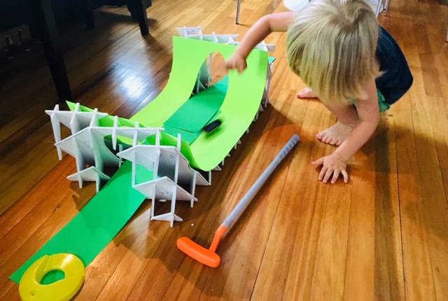
Children of all ages will enjoy the end result, so don't lose hope when doing this by hand. When I made my halfpipe it certainly made me appreciate what the laser cutter does, but at the same time it made me appreciate what's still possible by hand!


Having trouble? Let us know by completing the form below. We'll do our best to get your issues resolved quickly.
"*" indicates required fields
Great idea, Dan! I love the way you’ve organized the text and pictures of this lesson.